Hi Foo,
you are understanding the implications of a conductive amplifier chassis if there is a catastrophic mains failure in the PSU box. Even when the PSU box is made from a completely insulating enclosure.
I think the safety connection between the AMP box and the PSU box should go from chassis to chassis. The disconnecting network is what separates the Audio Ground from the Safety Earth.
It might help (belt and braces) to add a second or third disconnecting network in the AMP box from Audio Ground to Chassis. This may have implications for the audio performance of the amp. I have never built a two box PSU + AMP, so I'm guessing.
Can anyone offer advice?
Edited my previous post to account for AndrewT's input whilst I was replying to Pacific.
Fooboo 🙂
Fooboo 🙂
look up Leach low tim.fooboo said:Here's your reference to the RCA GND
quote;
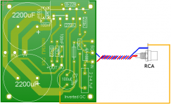
Add a pad to connect signal ground to the audio ground, but don't use it. Instead try connecting the RCA ground to the audio ground and the PCB signal ground goes back through the twisted pair to the RCA socket.
I am afraid I am not understanding this bit very well (sorry) and I don't know where to take the RCA socket GND or the Signal could you clarify for the hard of understanding
He explains all in there. In fact download the whole Leach paper and read it 20times until you understand every statement/calculation.
Take a twisted pair from the SG and -IN to the RCA. The SG goes to the barrel tag (or solder pot) and the -IN goes to the signal pole.
Take a single wire from the same Barrel tag to Audi ground.
If you have two RCAs connect the Barrel tags together with a short thick wire and run the middle of this wire to Audio Ground.
This RCA grounding seems to work more consistently for a wider variety of sources than grounding the PCB.
Hi Andrew
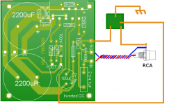
OK I have been reading Leach, Looking up audio and signal ground definitions in an attempt to get the No.2 brain cell to fire up 🙁 So here is a picture of what I think I understand to be the solution to the RCA connection. Twisted pair as expected plus an extra line from the SG tag of the RCA to the audio Gnd. Fingers crossed 🙂 If I have failed to understand feel free to drop the ACME anvil on me!
Regards
Fooboo
Attachments
the Audio Ground is off the PCB.
the Speaker Return, the disconnecting network, the Power Ground, the PSU zero volt, the Signal Ground, all go there. This is repeated for each channel. It's this repetition for each channel that prevents the Audio Ground going on the PCB.
If you are building a monoblock, you can design for the Audio Ground to be on the PCB.
Hi There
I think I saw in some pictures of other build a small piece of
copper clad PCB near each amp. Is this the audio ground
you refer to? Here is yet another attempt at understanding
the circuit. My apologies if I still missed it, I'm still reading
as much as I can.
regards
Fooboo
I think I saw in some pictures of other build a small piece of
copper clad PCB near each amp. Is this the audio ground
you refer to? Here is yet another attempt at understanding
the circuit. My apologies if I still missed it, I'm still reading
as much as I can.
regards
Fooboo
Attachments
Sorry but, no.
There is only one connection from Power Ground to Audio ground.
It comes from the PG pad between the caps.
There is only one connection from Signal Ground to Audio Ground.
It can be from either SG on the PCB or from the RCA barrel tag, but NOT BOTH.
A PCB is no good for your Audio Ground. Theoretically it should be a point and all connections to it should be at the same voltage. Audio Ground is a voltage reference for all the other circuits.
I use a nut & set screw with a series of solder tags bolted together. A solder tag is connected to each of the wires referencing that common voltage. You will find that the advantage of the bolted Audio Ground is that you can change the order of the tags. Some combinations are different from others. Experiment.
Change the speaker return label. It's confusing as it is. And make room for the speaker output like he said.
Hi There
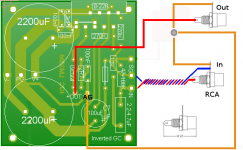
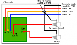
Well here I am again. Presumably the meeting point for the AG, SG, etc should be isolated from the chassis? here is another attempt to understand what is required. Sorry if I am wasting your time. If I miss it again I think I had better bugger off until I evolve into a more advanced life form. This is so bloody frustrating the circuit and principles couldn't be any simpler and yet I am having a hard time getting to grips with it........an apt signature I have 🙁 Just in case, the only thing I think is wrong this time is the audio out socket should have been wired in a similar fashion to the RCA in AG, -out as a twisted pair and a 3rd wire from the AG out of the socket to the 'common point'?
regards
Fooboo (clinically thick)
Attachments
remove the link AG to the bolted Audio Ground.
Take the 3twisted wires from the PCB power inputs and run them past the bolted Audio Ground. Connect the PG wire here.
Continue the +V-V to the smoothing caps and twist a third wire in with them. This third wire is the PSU zero volt line to bolted Audio Ground.
Add another connection to the bolted Audio Ground. This one runs to the Safety Earth. You can try running it direct or through a disconnecting network.
Finally add a speaker return to the bolted Audio Ground and run it as a twisted pair with the audio out to the speaker terminals.
Note that each flow and return is paired up and twisted together to minimise loop AREA.
The 3wire power supply consists of half a flow from +V and half a flow to -V twisted with the common PG line to cancel the net electromagnetic field.
If you can develop a physical layout that keeps each of the twisted sets as short as possible then you are going in the right direction. Choose a location for the Audio ground that facilitates this physical shortness. Now try to do that for the two channel amp. This is where thinking in 3D comes in real handy.
Thank you for your patience Andrew.
I will go away and think about this. Hopefully I will get it.
regards
Fooboo
I will go away and think about this. Hopefully I will get it.
regards
Fooboo
Fooboo
Don't lose heart with it, I'm sure you will enjoy the end product.
Are you starting to see why some people favour the point to point route yet?
There's no doubt you are learning much more this way than just assembling a board could have taught, so that's an added plus.
I also have the disadvantage of having a cat kicking about that can't resist anything it must leave alone. Etching solution would be just the thing to knock over no matter where I put it.
I had some floorboards up recently. It cost me several nice cat treats and a small amount of tuna to get the cat back out from under there so I could screw them down. I think I know which of us has been trained there!
John
Hi there.
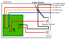
Well here's a wiring diagram of what I think you mean. I understand twisted pairs are essential to help minimize problems in the RCA and Speaker wire sets and the power run.
Thats something I guess. I used the same technique for all the bundles in my voice mod to prevent cross interference etc. Now I have obviously seen other PCB designs on here and I did notice on one of them that there was, for the audio in/out, only one pad a piece. So I presume that circuit used the off PCB audio ground to fix the returns to. Fingers crossed I have it now, he said hopefully for the nth time, because if I can't nail this wiring down I wont be building mine or anyone else's design. Thanks again.
Hi John. I can see the point 😀 . It's just bloody annoying. I did electronics as a hobby as a kid and had mixed results. Had a break and did some more in my later teens at which point I could see why I had had so many problems before. Now I am being really brave because audio was something I avoided like the plague because I understood there were 'rules', if you will, and I couldn't figure it out plus I had no access to self made PCB's. I read bucket loads then and on here looked at other designs to see if I can get the gist of the reasoning behind the layout etc. My biggest problem is I know, up to a point, what individual component do. Maybe not the why. But if you put a handful of components in front of me and tell me they make a flip flop circuit I'll take your word for it. Hold a gun against my head and tell me to build it my response is likely to be 'shoot'. I've built lots of circuits in my time converting from a schematic to vero board and had great success. My favorite past time was getting a circuit onto the smallest vero board possible. It's fun, I like doing it, but I get really aggravated by my lack of understanding even after I've read read and read again.............there rant over 🙂 Cats are cool, you just have to accept they are in charge. 😀
regards
Fooboo
Attachments
Hi Fooboo
I put Diptrace on my pc to see if I could get to grips with it, I can't.
It does give an idea of the design time/value for money ratio that the people who sell well designed pcbs to the diy community are working to. Another reason to salute them.
As far as the best place to learn about this stuff goes, you've already done the hard work by finding this place. I joined in 96 knowing much less than you do. I'm a car mechanic by trade so electrickery wasn't a total mystery, but I had the same problems getting away from the "live and earth only" mindset.
I know a little bit more now, what I know would fill a book, what I dont know would fill a library mindst.
Got to dash, I've got fish to cook.
John
I had national instruments software for a while. I simulated the voice mod in it
and ran virtual oscilloscopes and other tools in it. Good fun but I did learn that
it is only a guide not real world proof as the original sound to light part wouldn't
drive the bulb load that it did in software. Very clever though 'if' you really know
what your doing. I knew a bit but not enough. Since then I have changed my OS
to Linux so NI wont run in it. Fish for the cat? 😀
For my PCB patterns I use PCB wizard. You can draw in schematic or real world
or in schematic and have the software 'design' the PCB layout for you.............
However when I tried it the results were 18 link wires some of which spanned
the width or length of the PCB. The final pattern by hand had 5 links the longest
was 15mm..... Some times the ol' grey cells do work better.....if only they did with
the current problem 🙁
regards
Fooboo
Further study has revealed..........Yes I'm still at it.............Audio ground is also known as Star ground! I have also re found a thread on Star ground and it's use. Your good self, Andrew, played a large role in this thread and I have down loaded most of the images within that thread from the point where you placed the safety earth device in the debate.
It seems clearer now to me how it's done. Still some thinking to do but I was, with a lot of prodding, getting there I think. Would it be correct that I could lose the RCA in to SG line as it also goes to the Audio (star) ground? Or is there something I don't understand? Now I've stopped head butting the wall it doesn't hurt quite so much 😀 Fingers crossed I have at last had an epiphany!
regards
Fooboo
Here is what I believe to be the correct wiring of the circuit. This is based on the thread and illustrations within the star ground posts. I have also, I hope, adjusted the PCB such that the 2200uf caps segregate the power in triplet points from the rest of the circuit. Would it be Beneficial to rearrange the 3 components of the zobel/output set to shorten the AG line?
Of course thats if I have the wiring sorted now? I have seen a post where it was suggested that the zobel should be fitted to the output sockets. Or would that only apply if the distance between PCB and sockets was a bit long?
regards
Fooboo
Of course thats if I have the wiring sorted now? I have seen a post where it was suggested that the zobel should be fitted to the output sockets. Or would that only apply if the distance between PCB and sockets was a bit long?
regards
Fooboo
Attachments
post92 is correct.
The later post with the missing SG to RCA link will leave the Signal Ground floating and not tied to any reference. Further, currents flow in loops. The input signal current goes in and must come back out. The missing link prevents it coming out and break the source/receiver LOOP.
You could take SG to AG. That would re-establish the loop. BUT, the loop area of the signal flow and return would be enormous.
Hi Andrew
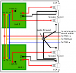
😀 Almost had it! I think I have it! New picture of a duel mono system unit one correctly wired as per a single circuit. Unit 2 hopefully wired in correctly including a link between the RCA in SG tags of both. ?.......................waits on tenter hooks................. Thanks for your help, I hope I am not wasting your time and actually getting there.
regards
Fooboo
Attachments
- Status
- Not open for further replies.
- Home
- Amplifiers
- Chip Amps
- Guidance for a 'beginner'