tomorrow I am re inventing the wheel
Save that for build number 2, as there will be a second if the first works first time. You wont be able to stop yourself and that's it, you are as lost to it as the rest of us.
Do I see a Dalek Tamp soundsystem in the offing? LandRover lights going strobey and a glowstick up your blaster!
For the purpose of a first build I would say stick with the bought circuit boards as any debugging will be easier with a well known quantity. That and all the possible mistakes and options are mentioned hereabouts.
I think I've heard the LM3886 is a bit more choosy about grounding issues than the LM3875, hum being your main enemy, and we don't want any of that.
Daniel
I will look into the kapton though I doubt I would get through a roll with my build speed. The time required to find inner peace is nothing compared to the time it can take to find my pencil.
Some say the T chip sounds better than the TF but we don't want to add anymore confusion to the myriad of options out there already for Fooboo!
John
Hi All
OK.........I'm capitulating!...............Will put some coin of the realm mad about sounds way 🙂
Dual mono 3886 PCB set here I come.......I'll just content myself with the build and making a bespoke chassis this time. A T amp would be wasted in yon Dalek 😀 theres a fine balance between being heard and fighting feedback in the confines of a MKIII travel machine 🙂 your glow stick up the blaster isn't far adrift. Some of the chaps have used clear acrylic tubing for their blaster and fitted a cold cathode in it 🙂
regards
Fooboo
the power supply side of post57 is correct.
The post59 supply has the -ve cap back to front.
I don't like the direct connection of power ground to signal ground on the PCB.
This is very easily sorted and offers options in grounding strategy later.
Break the Power ground at the bottom of the PCB. Insert two pads. Connect these pads with a resistor to separate the power ground from the signal ground. You can add a wire link on the back of the pcb to short out the resistor if you feel like experimenting with a direct connection, or you can omit the resistor and link and tie these grounds together at a central Audio Ground or at a chassis ground. That's four options and all it costs is two pads.
The ground from pin 7 is dirty, don't connect it to signal ground . Take it down to the power ground.
Similarly, the mute ground can also go to the power ground. This way only signal levels go to the signal ground and they are isolated from all others by that extra resistor we talked about.
Add a pad to connect signal ground to the audio ground, but don't use it. Instead try connecting the RCA ground to the audio ground and the PCB signal ground goes back through the twisted pair to the RCA socket.
The three wires forming the power input should be twisted as a triplet and brought to the pcb as a tight bundle. This will be your only power ground connection back to the PSU. connect the PSU to Audio ground.
Connect the Audio ground to the Safety Earth. I prefer to use a Disconnecting Network as described on the ESP site. But make it from high current, robust components. It may have to pass kA in the event of a mains wiring fault.
The PSU on post61 is corrected.
Can I assume the 22r has a 1uH air cored inductor in parallel to it?
Don't connect the speaker return to the -ve output on the PCB.
Take the speaker return to the Audio ground.
Agh! that 22r is supposed to be 0r22!!!!!
Hi Andrew
The circuit was tweaked some more last night as I found a 2.2uF-4.7uF poly cap with a smaller footprint. I have, I hope, implemented the changes you suggested though I doubt I got it right. The 0R22 is suggested as 'two 2 watt 0R47 carbon film resistors in parallel' on the DD site. I understand the PSU triplet but not the linking to audio ground.......but have seen and get the gist of the audio safety ground (I don't want to die for my music!) heres a pic of the current pattern.
regards
Fooboo
Attachments
Thanks AndrewT. I'm well out of my depth with board layout and design, as you can no doubt tell.
Fooboo
I saw the Dalek forum a while ago, there are some talented folks on there. I think I saw the thread regarding making the arm with the acrylic rod and the stainless spheres, very nice work.
I'm still chuckling about the "trundle of manic pepper pots"
John
Fooboo
I saw the Dalek forum a while ago, there are some talented folks on there. I think I saw the thread regarding making the arm with the acrylic rod and the stainless spheres, very nice work.
I'm still chuckling about the "trundle of manic pepper pots"
John
Hi Mate
Theres lots going on over on PD 😀 There was a mass trundle at the National Space Center in Leicester 2 weeks ago........they broke last years record for the number of daleks together in one place 😀
regards
Fooboo
Theres lots going on over on PD 😀 There was a mass trundle at the National Space Center in Leicester 2 weeks ago........they broke last years record for the number of daleks together in one place 😀
regards
Fooboo
Hi,
change that 22r label to 0r22.
Remove the Zobel connection from the signal ground and put it back on the power ground where it was before.
Break off pin2. Use the space to bring the power to pin4 without that dog leg.
Move the mute resistor down and that allows the PCB to be trimmed so that the chipamp can be bolted to the heatsink.
Break off pin11. If you want, you can close up all the small components and pads/traces and make your PCB much narrower (trim from the "k" of link up to the edge of the chipamp).
Make the 4 remaining traces coming to form the Sig G star meet at a point.
Consider adding a resistor to the trace from pin10 to SG. This will allow you to trim the output offset.
Do you intend labeling the PCB?
then swap the "+" input to "-in"
and swap the "-" input to "Sig G" or "SG"
This gets your ground connection clear and it reminds you that this is an inverting chipamp circuit.
Hi guys,
Sorry to 'crash' your thread Fooboo but is there room here for another Yorkshire newbie (or should I start my own thread)?
I've just ordered a set of LM3785 pcb's from Peter (AudioSector) and I'm scratching my head about a couple of things.

😀😀
Cheers,
Steve
Sorry to 'crash' your thread Fooboo
but is there room here for another Yorkshire newbie (or should I start my own thread)?I've just ordered a set of LM3785 pcb's from Peter (AudioSector) and I'm scratching my head about a couple of things.
😀😀
Cheers,
Steve
Hi All
Well here's the current incarnation. Pin 2 and 11 have been removed from the 3886 to allow better routing and compression. The unmarked res is the new addition which can be used for adjusting DC offset..........I will label the PCB properly once everything is as it should be.
Hi Dr X 🙂 It's probably better to start your own thread as information you receive to your
questions will be better available to others using the same chipset rather than lost in another thread. Welcome to the forum BTW. It's a great place to be. Liking the Dalek to 😀
regards
Fooboo
Attachments
Hi all
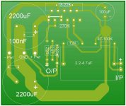
Found a circuit design with a PCB pattern. I have removed the jumper option for the mute switch and the variable resistor on the input has also been removed. This has allowed me to compress the layout somewhat and all components are still in their relative positions. Here is the web address of the site with this particular 'version'.
http://www.generalguitargadgets.com/index.php?option=com_content&task=view&id=58&Itemid=26
An 18V bipolar amp is recommended. Heres a picture of how I have adjusted the design. Note that the large 2W resistor has to have 10-12 turns of 22g wire wrapped around it.
regards
Fooboo
Attachments
Hi Foo,
does your layout perform better than that post72 version?
I think it will.
Try swapping the two input pads. It will save space and the length of that signal ground trace.
Change the labels on the inputs. It's going to confuse you and anyone else who uses your amp/PCB.
does your layout perform better than that post72 version?
I think it will.
Try swapping the two input pads. It will save space and the length of that signal ground trace.
Change the labels on the inputs. It's going to confuse you and anyone else who uses your amp/PCB.
Hi Andrew
Thanks for your patience. I have corrected the PCB as you have suggested. This also allowed me to trim the PCB size some more 🙂 Also added 3mm mounting holes in the corners. Is it also possible to put some values to the 2 additional resistors for future reference? Should The components marked with a 'range' of values be fixed at one value only for less confusion? The layout does look better I agree. Traces have more of a point to point path rather than going all round the houses which can only be good in the long run. I have looked at the ESP site with reference to the safety ground. It looks simple enough. Should one such device be fitted to each unit of the system or just fit one in the PSU unit and rely on the GND wire on the PCB's and interconnects?. I intend to fit my PSU separate from the amplifier. I do need to add a pad to the GND trace for the chassis GND wire, if I have understood, but I am not sure. I am re reading everything again 🙂 The output/zobel network could be given the same treatment as the input to reduce the SG trace length is this a good idea? All being well once I have built the real unit based on this PCB which is based on the DD P2P build I can put the PCB pattern and Silkscreen up for anyone who is interested.
regards
Fooboo
Attachments

the resistance seen by the +in & -in inputs of the chipamp should be the same to minimise output offset. However, with the inverting topology you have adopted, this would require a 270k resistor in the +in trace to SG.fooboo said:Is it also possible to put some values to the 2 additional resistors for future reference? Should The components marked with a 'range' of values be fixed at one value.......... Should one such device be fitted to each unit of the system or just fit one in the PSU unit and rely on the GND wire on the PCB's and interconnects?. I intend to fit my PSU separate from the amplifier. I do need to add a pad to the GND trace for the chassis GND wire
I would expect this to degrade the S/N ratio and you may want to try and fit a much lower value resistor and accept a small amount of DC offset.
You MUST fit a connection from Audio Ground to Safety Earth. This can be in the PSU box. But is it safe to rely on the detachable cable to provide the Safety Earth connection from the amp box to the PSU box. This has been discussed at length in other threads, but no firm conclusion was reached. It seems to depend on each builder's view of how safe is too safe.
You do not need an extra power ground pad.
andThe three wires forming the power input should be twisted as a triplet and brought to the PCB as a tight bundle. This will be your only power ground connection back to the PSU.
andDon't connect the speaker return to the -ve output on the PCB. Take the speaker return to the Audio Ground.
you have an inverting amplifier, so label it as such.then swap the "+" input to "-in"
Finally, the two 100nF decoupling caps in the PSU could be relocated much closer to the chip power pins. Extend the Power Ground trace up to the right to fill that space near the chipamp. now put in your two 100nF with the MINIMUM total length from + pin to cap to PG to cap to -pin. Consider also adding a larger cap from +pin to -pin. See Carlos FM snubber PSU for details of value.
Hi Andrew
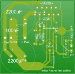
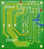
OK I think I followed most of that. I have moved the 100nF caps as close to the Chip as possible. Also having checked CarlosFM's snubber PSU as directed I have added a 3.3uF that is between the + - (Pin 1-5, 4) The carlos PSU is what I will be building as the PSU for my amp. I have marked with a red arrow this extra cap and the resistor that I have given the nominal value of 270K. Correct so far? Now I haven't moved the SG out yet. I have coloured it orange for clarification at this time. This is the trace I need to move to the Audio ground..........Audio ground is the same as Signal ground (the star ground coloured blue?) The Power star is the point marked with a large green dot? I have also changed +IN to -IN.........I'm slightly confused at that point. Is this because it is the Vin- (pin 9) of the LM3886 it goes to so as you say I am using it as an inverted amp? I am still at the stage where thinking in terms of +ve and -ve as the be all and end all though I am starting to get a grip with the subtle variations.
I am all for safety as regards the safety earth etc. So the Ground of the Triplet is only for the circuit itself. But I need to ensure that the metal chassis's are earthed so either an extra wire must be run in the interconnect and use the case of the plug or a pin to effect the connection of the case to earth. Either that or if the system is stacked as I am looking to a strap will be used to bond the chassis together. Any hoo here's the image of the current layout colour coded for my clarity 😀
regards
Fooboo
Attachments
Hi All
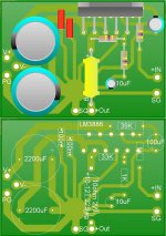
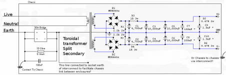
Well apart from the actual GC itself which I am in the throes of designing my own PCB for, with a large portion of help from AndrewT, The PSU needs looking at as well. CarlosFM's design seems to be a good choice and I will also add a safety earth to the PSU as per the Andrews advice and is taken from the information at the ESP site. Here is a composite image I have made of the PSU and the safety earth. I think I have it right. Now my PSU will be a separate unit and linked to the Amp via an interconnect. Now I understand that all the audio In/Out sockets must be isolated from the chassis lest we bypass the safety earth. But I have an amplifier chassis that is metal and in the event of a major cockup/failure may be live!!!! Is the answer to add a line in the interconnect, in addition to the live, neutral, earth, that connects only the chassis's together? Or should a ground wire come from the safety earth to be used as the chassis earth between separates?.........I may not be explaining myself very well here I know.
regards
Fooboo
Attachments
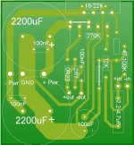
I wonder, if your Cin is really so narrow. I remember 2,2-4,7 µF to be much wider. The size of that additional 3,3 µF capacitor also seems quite optimistic.
From a practical point of view you should consider that you also have to connect wires somewhere. At least the connection points PG, V+ and +OUT are very near to the 2200 µF capacitors. It will be difficult to connect and route the wires to those points.
Just a stomach feeling, but I would try to make the PG connection so that the 2200 µF capacitors are physically and electrically between it and all other components except for the speaker return.
Hi,
the orange connection from the Zobel to the Power Ground MUST remain.
The Audio Ground is where all the grounds meet at a central star location. This is usually off PCB and with a multi-channel amplifier must be off PCB. A few manufacturers may put the central Audio Ground on the PCB but this is a compromise to economy over performance and takes great skill in understanding grounding to get it to work properly.
The Signal Ground is for signal levels ONLY. Do not take any other connections to the Signal Ground. Remember that RCA advice I gave, you must at least try that as a solution.
Hi All
I double checked the caps just in case. I am glad to say they are available in large and small physical forms.........phew pitch 7.5 mm so only a small change to make with those two.
Here's your reference to the RCA GND
I am afraid I am not understanding this bit very well (sorry) and I don't know where to take the RCA socket GND or the Signal could you clarify for the hard of understanding
Safety Earth got it! 😀
Thanks for your help Gentlemen much appreciated
regards
Fooboo
I double checked the caps just in case. I am glad to say they are available in large and small physical forms.........phew pitch 7.5 mm so only a small change to make with those two.
Here's your reference to the RCA GND
Add a pad to connect signal ground to the audio ground, but don't use it. Instead try connecting the RCA ground to the audio ground and the PCB signal ground goes back through the twisted pair to the RCA socket.
I am afraid I am not understanding this bit very well (sorry) and I don't know where to take the RCA socket GND or the Signal could you clarify for the hard of understanding
Safety Earth got it! 😀
Thanks for your help Gentlemen much appreciated
regards
Fooboo
- Status
- Not open for further replies.
- Home
- Amplifiers
- Chip Amps
- Guidance for a 'beginner'