Nuuk Tempt away, you haven't been wrong so far! Does it use the 3875? I've got a pair sat waiting for something to do with them.
Yes, they would be fine. Shine up the pins up, turn on the iron and stand by.......

Nuuk
Standing by, giddy with anticipation!
fooboo
See what he does to people? Don't say I didn't warn you when you are knee deep in chipamps and god knows what else.
John
Standing by, giddy with anticipation!
fooboo
See what he does to people? Don't say I didn't warn you when you are knee deep in chipamps and god knows what else.
John
Hi all
Well that's the plan then I will gradually assemble what I need to start the circuits. make do with PC and my current HiFi speakers so I can test and at last work the resulting amp. 🙂 I can weald most woodworking tools as wel so cabinet making for speakers is not a problem. What really gets my interest other than the chance to play with electronics and woodwork is getting a high quality audio system far cheaper than I had ever dreamed of. It's a good challange and doable to boot! Watching Nuuk's hinted at surprise will be interesting to see..........
regards
Fooboo
For inexpensive, good-sounding speakers that are fun to build, search for Cyburgs projects Needle, Brick, Viech, etc. You could be left with spare money from your speaker budget.
Hi Pacific.
I have had a quick look, I'm fitting new skirting boards in the bedroom 😀 , and Cyburgs designs are very nice in all aspects. 🙂 This just gets better and better 🙂 Thanks everyone for your help and guidance. BTW Pacific I was born in Dusseldorf 🙂 and lived in germany until I was 5. One day I inten to come back to look up my old haunts 🙂
regards
Fooboo
Hi all
Well I have pretty much read myself to death. So much so, infact, I have no idea what I'm doing 😀 . OK here's where I think I will start, after Christmas. Order an LM3886 Dual Mono Chip Amplifier PCB Set from Mad about Sound. I have Dl'd the instructions already 🙂 . Sourcing the parts thereafter looks easy enough. What are the esteemed members thoughts on using a single supply to run both units or of using a dual supply, I understand the cost implication. My Intention will be to run a CD player as source so what is the 'best' attenuator to use to augment the input from the player. I have seen the stepped attenuator, I think I can do that, the 'standard' Log taper potentiometer, or a linear taper pot with a resistor fitted to create a log 'action'. I am interested in a pair of FS125 Drivers and have seen a plethora case designs. What are your thoughts on, a sealed case or something along the lines of cyburgs needle. I do intend to have a look inside my Akai speakers and see what drivers are in them and whether they would be good enough to use.
As previously mentioned I can stream my music from my PC to my Xbox which then plays through the TV. Has any one any experience/comments of the quality of the signal the Xbox produces if I was to use it as the link to my intended amp or even as the CD player. I am aware of the PS1 in this respect. Are the other methods of streaming from PC to amp that are simple, inexpensive?
All prods in the right direction gratefully received. Is there a point to point part by part pictorial guide of the basic GC circuit as seen on the rather wonderful DD website. I have seen the image of the complete built circuit but for confidence sake a bit by bit picture set would be handy.
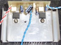
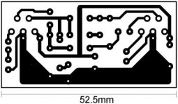
Here's a couple of pictures of the TDA2003 circuit I built. The original circuit was in an EPE mag. Their PCB pattern was originally around 100mm long but with a little messing about I was able to reduce it to 53mm. All the components are still in their relative positions I just changed the resistors so the are vertical instead of horizontal and rotated a couple of the polyester caps 90 degree's to aid the contraction of the circuit.
regards
Fooboo
Well I have pretty much read myself to death. So much so, infact, I have no idea what I'm doing 😀 . OK here's where I think I will start, after Christmas. Order an LM3886 Dual Mono Chip Amplifier PCB Set from Mad about Sound. I have Dl'd the instructions already 🙂 . Sourcing the parts thereafter looks easy enough. What are the esteemed members thoughts on using a single supply to run both units or of using a dual supply, I understand the cost implication. My Intention will be to run a CD player as source so what is the 'best' attenuator to use to augment the input from the player. I have seen the stepped attenuator, I think I can do that, the 'standard' Log taper potentiometer, or a linear taper pot with a resistor fitted to create a log 'action'. I am interested in a pair of FS125 Drivers and have seen a plethora case designs. What are your thoughts on, a sealed case or something along the lines of cyburgs needle. I do intend to have a look inside my Akai speakers and see what drivers are in them and whether they would be good enough to use.
As previously mentioned I can stream my music from my PC to my Xbox which then plays through the TV. Has any one any experience/comments of the quality of the signal the Xbox produces if I was to use it as the link to my intended amp or even as the CD player. I am aware of the PS1 in this respect. Are the other methods of streaming from PC to amp that are simple, inexpensive?
All prods in the right direction gratefully received. Is there a point to point part by part pictorial guide of the basic GC circuit as seen on the rather wonderful DD website. I have seen the image of the complete built circuit but for confidence sake a bit by bit picture set would be handy.
Here's a couple of pictures of the TDA2003 circuit I built. The original circuit was in an EPE mag. Their PCB pattern was originally around 100mm long but with a little messing about I was able to reduce it to 53mm. All the components are still in their relative positions I just changed the resistors so the are vertical instead of horizontal and rotated a couple of the polyester caps 90 degree's to aid the contraction of the circuit.
regards
Fooboo
Attachments
Bookmarked! Cheers for that. It's very elegant isn't it 🙂
Input Input! 😀 I've been reading the thread on Star
ground etc.........I'll get there once the pain goes away!
regards
Fooboo
Input Input! 😀 I've been reading the thread on Star
ground etc.........I'll get there once the pain goes away!
regards
Fooboo
Yes very true. Roll on Christmas. Then I can get the bit's. I think I am recanting 😀 The P2P looks way easier now I have some visual reference so I think i'll swing with it. Just out of curiosity what is the actual purpose of a pre-amp as defined by audio buffs. Is it just to match source impedance/line level to the power amp's needs and or condition the signal?
regards
Fooboo
regards
Fooboo
fooboo
If you fancy something other than star grounds to be thinking on, there are some very nice chassis construction ideas on here.......
http://www.vikash.info/audio/
The ported FR125 design of his is the one I use here, apart from mine not being all shiny and lovely. And mine look like they've been nibbled by wolves rather than skillfully crafted. That aside, they're identical.
I'm very happy with the sound but can't help wondering what they would sound like in bigger boxes, maybe some bibs but sadly not Harveys.
John
Just out of curiosity what is the actual purpose of a pre-amp as defined by audio buffs. Is it just to match source impedance/line level to the power amp's needs and or condition the signal?
1 Impedance matching between source and power amp.
2 Gain if required.
3 Volume control if required.
4 Input switching if required.
5 Something else to build.
Hi all
Thanks John, Lovely little set of enclosures! Thanks Nuuk It seems I am getting some sense of what's what. So build the basic GC using DD and the Dogbreath pictorial build including the snubberised PSU. As is I can then use this as an 'integrated' amp, so called, because it boosts the input and has the volume control all in one? Later when I have a vinyl deck and or tuner to go with the CD player I can build a pre amp to provide a convenient point to act as, switcher, impedance matcher in case of a disparity, gain for the vinyl player, and I can move the attenuator from the power amp input to the pre amp output if I so wish. If and when I build the pre amp I need to either adjust the gain downwards in the power amp to 20 orrrrrrrrr put a 220R resistor inline with the input signal line 🙂 I'm getting it aren't I.
Great stuff Chaps thank you for your patience
regards
Fooboo
No worries. I'm only new to this myself so I will leave the clever stuff to those far more qualified than I.
I will be over to see my folks and hang with my homeies (as I believe the young people say) at some point over the next few weeks. I can chuck a chipamp and speakers in the car if you are reasonably close to the Dewsbury area and fancy a listen.
Hearing roughly what you will have at the end it will make the job easier, assuming of course you like what you hear. If you don't like the sound, then at least you know without spending your hard earned to be disappointed. It's a win either way. Do you have a big teapot?
John
Hi All
Alas I am going on the 'tedious' Christmas run. All the way down South to see my dad, little brother, and my daughter until the new year otherwise thats a belting idea 🙂 . Today I have been pricing up the components for the Mick Feuerbacher 3 resistor amp and his CarlosFM based snubber PSU. The PSU, Amplifier, components only + the traffo comes to a grand total of £84.04 Not bad I'm guessing especially if it performs as all the luminaries here say 😀 . With the I/O ports for power/Audio, standoffs, pot, and various hookup wires I guess it will cost a little over £120 then theres the cases to think about though these are less important at this time and during building and testing. Though I am considering what my options are especially if I then upgrade to a pre-amp, switcher in the mix as I will want to have matching enclosures. Whether these are hand made, off the shelf, or recycling are also considerations. One small question if I may. As and when I get a CD player to use with the amp (and boy I've seen ARcam players going for peanuts on E-bay 😀 ) How do I determine whether the source is already decoupled on it's output so I know whether I need to add decoupling or not to the input of the amp. If I needed to apply decoupling to the input is this simply a capacitor in series with the input signal line, is an electrolytic or a non electrolytic how do you determine the value you may need especially if you only have a multi meter to test everything.
regards
Fooboo
Fooboo
Pity you're not around over the holidays, there's always next time.
If I remember rightly there was some discussion about changes that could be made to the 3 resistor amp, some thought it too minimalist for stability (I think) I will have a search tomorrow and try to track it down.
Yet more useful reading.... http://www.allaboutcircuits.com/
Theres lots of it!
John
Fooboo, the short answer to your question is that if you have DC coming from the previous part of your system, you need a DC blocking cap on the input of the next stage. Most commercial hi-fi will already have a DC blocker on its output but it is always best to check by measuring.
Thanks guys
With all the study I'm doing the DD GC is looking a lot easier to do than I first thought. It also has a DC Blocker on it already so it's prepared either way 🙂 Also having switched brain on the expected output type of an amp should be 'AC'. I am working this out from a circuit I have built which has a sound to light unit on it. This uses an opto-isolator on which the signal input is half rectified by a diode so the internal isolator diode gets DC to work from the original audio signal. Sos the line out from a source should be 'AC'? The only other thing I would need to do to the DD GC is change the 2 1000uF caps as per CarlosFM's PSU instructions to a pair of 2200uF caps with a 100nF poly cap in parallel. So Far so good 😀 . Now power stars and signal stars I understand the primary thing here is to centralise power distribution which helps keep interference down and avoid GND loops. Looking at all the guides and builds I have come to the conclusion that part of the trick to keeping the audio clean is to use a smaller guage wire. I say trick but it's based on true physics of course, electricity takes the least line of resistance soooooooo the lighter gauge audio wires having a higher resistance in comparison to the power lines so there is a bias which means the electricity flows from the audio to the power. The long and short of it means that any 'noise' in the DC lines is unlikely to present itself in the audio lines because of the 'bias'. Close? or should I be shot down in flames??
regards
Fooboo
electricity flows from the audio to the power.
Badly worded lets say the power in the smaller wires has a bias towards the heavier wires so in theory anything going on, within reason, on the DC power traces/wires doesn't show in the audio traces/wires.
regards
Fooboo
- Status
- Not open for further replies.
- Home
- Amplifiers
- Chip Amps
- Guidance for a 'beginner'