well, no worries. I'm going to build a tube preamp which will solve any problems that may arouse.
On the other hand I don't even need the new power amp. I have a Densen Beat B-300XS poweramp but I might use the Gainclone to drive my center speaker instead of mid class AV receiver. If it really kicks *** I can add a few channels and replace the whole power amp of the AV receiver. I might build one cheap amp for my buttkicker also 😉
http://kotiweb.kotiportti.fi/audiovideo/munht/taristin/taristin.html
a video 😀
http://kotiweb.kotiportti.fi/audiovideo/munht/taristin/sohvataristin3.wmv
😀 😀 😀 That is really somthing funny. Hey DIY Audio members will we have video tutoring in the future haha.
Re: Center tapped x-former
There are quite a few posts on the subject. I read Sherman's post and yours that mention going like this: Outside wires from center-tapped secondaries go to AC1N and AC2H while center tap goes to AC1H and AC2N.
Meanwhile, in Brian's new users guide, chapter 3.1 goes like the attached picture. Why would someone want to use Brian's solution over the previous one ? Is any of the two solutions better than the other ?
Please do. It'll be interesting to see if there is a difference after all.
Some people do it for the money, others for the fun of it. Guess where Brian stands 😀
rabstg said:It looks to me like your power supply is wired up wrong. You need to wire the AC1H and AC2N to the center-tap on the transformer, which forms the PGND connection. I would recommend swapping this and checking your power supply voltages."
There are quite a few posts on the subject. I read Sherman's post and yours that mention going like this: Outside wires from center-tapped secondaries go to AC1N and AC2H while center tap goes to AC1H and AC2N.
Meanwhile, in Brian's new users guide, chapter 3.1 goes like the attached picture. Why would someone want to use Brian's solution over the previous one ? Is any of the two solutions better than the other ?
rabstg said:I have several transformers I bought from Steve @ Apex so I am going to evaluate the sound with each pwr option on the diagram.
Please do. It'll be interesting to see if there is a difference after all.
rabstg said:BTW, I can not believe the support we get from Brian. You don't get this level of support from Hi-end manufacturers much less a $35-75 kit!
Some people do it for the money, others for the fun of it. Guess where Brian stands 😀
Attachments
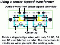
moving_electron said:In section 3.1 of the new manual it states:
"The original standard application of this kit uses the first, a transformer with dual secondaries. For this application, the primaries are attached to the mains, while V+ and 0+ are attached to PG- and V- and V- and 0- are attached to V- and PG-."
Is this what it is really supposed to say??
It's late here but this doesn't make any sense to me.
This was a typo in the manual, it should have said:
"...while V+ and 0+ are attached to PG+ and V+ and V- and 0- are attached to V- and PG-."
I have corrected this and updated the posted manual.
Here is an alternate explanation of what is trying to be conveyed:
For the standard power supply configuration for the kit, a transformer with 2 pairs of secondary windings should be used. The rectifier pcb is setup in a dual bridge rectifier configuration, where each secondary is rectified to DC, then the dc voltages are referenced to ground on the amplifier pcb to obtain +V and -V. To wire the input AC from the secondaries into the rectifier pcb, wire 1 pair of secordaries into the AC1H and AC1N connection pads on the rectifier pcb, ane the other pair of secondaries into the the AC2H and AC2N pads. For the transformer primaries, they should be connected to the AC mains with a fuse in series with either the hot AC line, or two fuses, each in series the neutral and hot AC lines. If your transformer has dual primary windings, it is able to be configured for both 110vac/220vac AC mains for domestic (us) or overseas usage. [parallel mains 110vac for US, and series mains for 220vac] (Avel Lindberg transformers have dual primary windings for this purpose)
I wrote this up real quickly and haven't put time to proofread it, but I will add a similar text to the manual, assuming that I correctly wrote the above paragraph.
--
Brian
Well, from what I've read:
Brian's solution to a center tapped transformer works!
BUT it use only a single bridge rectifier, which is not considered as high end as the double bridge.
Sherman's solution makes knowlegable people nervous, and another person hasn't been able to duplicate his success, but it works for him , and allows the use of a dual bridge. Unlike cold fusion, Sherman has a functioning gainclone to show.
I am hoping soon to try Sherman's approach because I have some center tapped transformers and want to use them and I don't know any better. How can Sherman's work? Bad solderjoints? or: HE's RIGHT!!! We need to find out!!
It is easy to get confused by the power supply and assume that one bridge is for each channel, and that 2 of the wires from the transformer go to each channel. This is NOT how it works. The power supply outputs are shared in parallel with as many channels as you think prudent to attach. If you want a separate bridge or separate transformer and bridge, per channel, you need to use an entire power supply circuit board for each channel. This is why Brian now includes 2 rectifier bridge boards in each order.
There are two reasons to use 2 transformers:
First, if you want a separate transformer for each channel- you need 2 transformers with dual outputs-(4 wires out) (or center tapped if the above works).
Second: you have 2 transformers with only single outputs (2 wires out)
and you want to combine them to act like a single transformer with dual outputs- (4 wires out) In this case the transformers are shared between the channels.
Order question
Hallo Brian
I am from Denmark in Europe. One of my danish friends
is in Texas and will go back to Denmark in 8 days. Do
you think there will be time enough for him, to bring
me a GC kit if I place the order today?
Thanks for all the effort you and others have put into the GC
kit, it is appreciated also in Denmark.
Kind regards
Anders
- I posted this message to your email aswell. I'am sorry for double posting, but I would like to place the order asap.
I could not manage to get Sherman's method to work, but that may have been because I was trying to parallel two transformers at the same time. I think I blew 5 fuses trying to get it to work.
My solution was to not even use the power supply pcb that was supplied, and just made two rectifiers (one for each channel) with the 8 diodes. That worked wonderfully, and gave me two monoblocks. Just a suggestion for anyone out there that wants to use a CT. 🙂
My solution was to not even use the power supply pcb that was supplied, and just made two rectifiers (one for each channel) with the 8 diodes. That worked wonderfully, and gave me two monoblocks. Just a suggestion for anyone out there that wants to use a CT. 🙂
Variac said:...transformer stuff...
If you are stuck with a centertapped transformer, if you peel back the wrapping on it, you might find that it is actually dual primaries, with the windings tied together to make a center-tap. I have heard of a few instances of this.
As for the single bridge not being high end... it might be a slight tradeoff, but my solution of the single bridge appears to work. With the dual bridges, my concern is that ground loops might be created, since the GND connect is tied together at the transformer, then seperated, then tied together again. If only a single ground connection to the amplifier pcb is used from the power supply board, then this problem might be avoided.
As for using dual transformers to form a single supply, if the samples are not exactly the same, the DC levels might vary a bit more than using a single transformer with dual secondaries, causing additional dc offset.
I would recommend trying different power supply configurations, without the amplifier pcbs connected, then see if the DC voltages come out correctly with a multimeter. Also, keep safety in mind, wearing safety googles and carefully handle the mains.
--
Brian
mateo88 said:I could not manage to get Sherman's method to work, but that may have been because I was trying to parallel two transformers at the same time. I think I blew 5 fuses trying to get it to work.
My solution was to not even use the power supply pcb that was supplied, and just made two rectifiers (one for each channel) with the 8 diodes. That worked wonderfully, and gave me two monoblocks. Just a suggestion for anyone out there that wants to use a CT. 🙂
The current kits come with two rectifier pcbs, so a single bridge could be assembled one each, with the wiring shown in the user's guide, using the available parts. For the basic kits, 100v 4.7uF fc capacitors are included, so that they could be used with a single bridge, across +V and -V without overvoltage problems.
Then, each single bridge pcb setup would power one channel.
--
Brian
Yeah, I have the old kits, though, so I just made pretty little diode squares and plopped the capacitor on top. I actually like it that way, nice and compact. 🙂
I agree with all Brians says above.
The single bridge is probably fine. I suspect I couldn't tell the difference. It just bugs me a bit to have 2 separate transformers to get ultimate fi and then have to compromise on the single bridge vs. double.
Using 2 transformers with single secondaries to act like one is not "endorsed" by some people, but there is a lot of interest in it because people have transformers lying around....I guess it can work..
BrianGT said:
As for using dual transformers to form a single supply, if the samples are not exactly the same, the DC levels might vary a bit more than using a single transformer with dual secondaries, causing additional dc offset.
Inbalance in rail voltages doesn't affect DC offset. With batteries, I sometimes have as much as 2 volts of a difference and the DC offset always stays the same.
Also, if one rail disappears, it will not produce any dangerous DC at the output: The amp will just not play, but the speakers won't get damaged.
BrianGT said:If you are stuck with a centertapped transformer, if you peel back the wrapping on it, you might find that it is actually dual primaries, with the windings tied together to make a center-tap. I have heard of a few instances of this.
I actually did just that during my lunch hour. I'll be using two Chia Yu 2 X 21 V toroidals from Apex Jr for my monoblocs so I peeled the wrapping from one of them and found the two leads tied together. I'll split them up so that I get two secondaries. 🙂
Since I haven't received my kit yet
 I'll have plenty of time to rewrap the two transformers and get my soldering iron ready 😉
BrianGT said:
This was a typo in the manual, it should have said:
"...while V+ and 0+ are attached to PG+ and V+ and V- and 0- are attached to V- and PG-."
This could be interpreted as V+ attaches to PG+ and 0+ attaches to V+.
It might be clearer if it read:
"...while V+ and 0+ are attached to V+ and PG+ and V- and 0- are attached to V- and PG-."
Great work on the manual. From experence I know it is really hard to set things down in words given the different ways other people will read and interpret it.
"I have made this letter longer than usual,
only because I have not had the time to make it shorter." - Blaise Pascal
moving_electron said:
This could be interpreted as V+ attaches to PG+ and 0+ attaches to V+.
It might be clearer if it read:
"...while V+ and 0+ are attached to V+ and PG+ and V- and 0- are attached to V- and PG-."
Great work on the manual. From experence I know it is really hard to set things down in words given the different ways other people will read and interpret it.
"I have made this letter longer than usual,
only because I have not had the time to make it shorter." - Blaise Pascal
You are quite correct. I fixed it yet again:
"...while V+ and 0+ are attached to V+ and PG+ and V- and 0- are attached to V- and PG-."
Thanks for pointing that out. The pdf is now updated on the website.
--
Brian
Here is an example of what not to do when wiring up your center-tapped transformer:
If you look closely, you will see that half of the centertap secondary is shorted out/reversed in polarity. The transformer is a 42vac center-tapped transformer, meaning that 21vac-0-21vac is desired with respect to the center-tap being ground. The two wires that go to the center-tap should go to the AC1H and AC2N connections on the pcb.
Be careful not to do this, as might possibly blow up capacitors, blow fuses, ruin chips, etc...
The primary AC connection is not shown in this picture, but make sure that a 3A or similar slow-blow fuse is connected in series with the primary hot AC wire (or both the hot an neutral wires).
As for the strange triple primaries, they are wired correct, as this is a surplus Chia Yu Co Ltd transformer from Apex Jr:
"42Vct For 120V input tie the 2 Blacks and Brown together along with Tying the 2 Whites and Blue together... Output the left over 3 wires"
http://www.apexjr.com/miscellaneous.html
--
Brian
An externally hosted image should be here but it was not working when we last tested it.
If you look closely, you will see that half of the centertap secondary is shorted out/reversed in polarity. The transformer is a 42vac center-tapped transformer, meaning that 21vac-0-21vac is desired with respect to the center-tap being ground. The two wires that go to the center-tap should go to the AC1H and AC2N connections on the pcb.
Be careful not to do this, as might possibly blow up capacitors, blow fuses, ruin chips, etc...
The primary AC connection is not shown in this picture, but make sure that a 3A or similar slow-blow fuse is connected in series with the primary hot AC wire (or both the hot an neutral wires).
As for the strange triple primaries, they are wired correct, as this is a surplus Chia Yu Co Ltd transformer from Apex Jr:
"42Vct For 120V input tie the 2 Blacks and Brown together along with Tying the 2 Whites and Blue together... Output the left over 3 wires"
http://www.apexjr.com/miscellaneous.html
--
Brian
fireman said:
I actually did just that during my lunch hour. I'll be using two Chia Yu 2 X 21 V toroidals from Apex Jr for my monoblocs so I peeled the wrapping from one of them and found the two leads tied together. I'll split them up so that I get two secondaries. 🙂
Since I haven't received my kit yet
Excellent! Having them seperated will make life easier.
As for my previous post, this is a Chia Yu transformer also from ApexJr, so it should be able to be split up also and wired in the recommended manner.
--
Brian
Dimensions of assembled board?
Hi!
I'm still to receive the boards i ordered, but im running out of time off 'work', so i have to start work on my chassis soon!
Could anyone tell me the height of the panasonic 1500uf caps as well as the 'vertical' distance between the bottom of the lm3875 and the the board?
Also does anyone know if the caps can be mounted on the underside of the board without any modifications?
Any help would be greatly appreciated!
Thanks, Nik. 😎
Re: Dimensions of assembled board?
--Ferdi
Hi Nik, the exact height of the 1500uF Panasonic FC cap is 35.3mm and I see no problem in mounting them on the underside of the PCB. I am not exactly sure what you mean by your other question, but the distance between the top of the PCB and the bottom of lm3875 package is 3.2mm. Hopefully that helps.Beggar said:Hi!
I'm still to receive the boards i ordered, but im running out of time off 'work', so i have to start work on my chassis soon!
Could anyone tell me the height of the panasonic 1500uf caps as well as the 'vertical' distance between the bottom of the lm3875 and the the board?
Also does anyone know if the caps can be mounted on the underside of the board without any modifications?
Any help would be greatly appreciated!
Thanks, Nik. 😎
--Ferdi
- Status
- Not open for further replies.
- Home
- Group Buys
- Group order of non-inverted LM3875 pc boards? Anyone interested?