Not much I can say about it though. The APL_TDA software claims 10x better time resolution than the normal FFT approach REW uses. I'm not enlightened enough to know if that claim is true yet.
But it is interesting to compare these results. But I don't know which one actually is closer to the truth.
I cant really reach any meaningful conclusions either. Nor can I say which best describes what I hear or which is the most accurate.
Thanks Jim, for playing along here, much appreciated. I wanted to see two things:
One, did you achieve the goal of integrating your speakers and subs with the least group delay without using digital (FIR) correction.
While the topic and goal of this thread was about minimizing GD, it is only one among many in the overall scheme of my sound room. Since back in May and June when the majority of this thread took place, i have actually managed to make the GD worse 🙁 This is due mostly to increased magnitude in the lower bass region, and the removal of boosting the extreme low end. Basically, tonal balance is more important to me than sacrificing low end magnitude for the sake of lower GD. So my 40hz GD at one point was around 11ms, now its around 15 or 16ms.
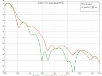
But lets think about the original goal: A tighter and better behaved low end. While GD certainly is one measure of such, it is not the only one. Decay plays a role as well. If you look at the attached graph, this shows where i was back in June (orange)vs now (green) with a banded 1/1 63hz ETC. Generally, the lows decay a little more quickly than before (after 28ms). Another way to look at the difference is how long does it take to get to -30db and -40db.
-30db: 60ms before, 52ms now.
-40db: 67ms before, 57ms now.
Is this significant? ???
So, Is GD or decay more important? I really cant say.
Two, How do the measurements suites compare, your room is the best I've seen in measurements and as such a very interesting case for comparison.
If the question here is whether I like REW or APL-TDA better, REW has more tools. APL-TDA may render spectrogram visualizations better. REW is free, APL-TDA is not.
Attachments
Last edited:
I can agree to that, the group delay in itself is not the only thing to look at. My plot shows the minimum phase tracking, following the behaviour of my low frequency response roll off.
I've had shorter group delay by using a more linear phase correction, but the one I use now, following minimum phase, sounds more natural to me.
Tonality or tonal balance is a high on my list of priorities as well. So I can relate.
Still I personally strive for getting true time coherency within my speakers band width. Because even that influences the tonal balance i.m.h.o.
For me it's not about choosing between measurement suites. I've used REW throughout all my corrections. But the opportunity to check the result with the APL_TDA software was nice. I'd love to know if the writer's claim that it's better behaved in the time domain is valid.
Either way my plots have improved over the last year and the enjoyment factor has gone up. That's what counts, right?
Last edited:
I applaud your time coherency approach. But lets explore this concept a bit. If I am understanding your goal and the data properly, the step response describes the first wavefront timing. This is usually viewed in the first 5-10ms or so.
One could say that decay describes the last wavefront in a sense. In other words, there is a point where perceptually the tone in question is no longer audible as it decays.
Now, I could probably agree that the first wavefront may hold more importance over the last in the same way that the direct response dominates what we hear over the room response. But I think we can agree that the room response is still important.
So, shouldn't true time coherency factor in the entire temporal response?
It is, at the end of the day, about perception. And enjoyment factor as you put it certainly is paramount. Yes, that is what counts!
Last edited:
True points, all of them. I did tell you about my speakers being in a living room, right 🙂. That's part of the reason why I chose Line Arrays to get to my goals. In our plots you can see my room has more contribution to the sound than yours. No doubt. But also look at wave shapes at different frequencies within the bandwidth played by our speakers. You know, the entire square wave discussion. My approach tries to stay as true as possible to that original wave shape. Your approach tries to limit room effect on perception as much as possible. Ideally I'd like to do both. But I can't. So I maximise what I can do.
When playing a full bandwidth signal, my speakers will be done sooner than yours though (lol). We can see so in the graphs. 😀
My room will still be humming long after yours is dead quiet too 😱
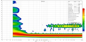
Let's compare:

This is both our plots next to each other. I don't know the lower level of the plot but I'd guess it's about -20 dB into the blue area.
So a chord played on a guitar would have all it's harmonics delivered in a very short time with my plot. Depending on frequency contents of coarse. Mine will last a little longer at stightly higher than ~-20 dB levels.
That same chord played on your speaker will be more spread out if the frequency content covers a large spectrum. It will die out way sooner and drop below that -20 dB sooner. The big question: which chord would sound closer to an actual guitar being played in the same room.
Just dropping my theory here, hope you don't mind.
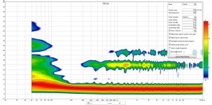
When playing a full bandwidth signal, my speakers will be done sooner than yours though (lol). We can see so in the graphs. 😀
My room will still be humming long after yours is dead quiet too 😱
Let's compare:
This is both our plots next to each other. I don't know the lower level of the plot but I'd guess it's about -20 dB into the blue area.
So a chord played on a guitar would have all it's harmonics delivered in a very short time with my plot. Depending on frequency contents of coarse. Mine will last a little longer at stightly higher than ~-20 dB levels.
That same chord played on your speaker will be more spread out if the frequency content covers a large spectrum. It will die out way sooner and drop below that -20 dB sooner. The big question: which chord would sound closer to an actual guitar being played in the same room.
Just dropping my theory here, hope you don't mind.
Last edited:
While how you describe my room is basically correct, it is not my goal to eliminate the room entirely.
If the best sound was derived simply from making it dead as possible, then the task would be fairly easy. Just put 18" of pink fluffy (attic insulation) on every surface 😀
But some of what I have explored further since last summer is what room reflections we need. The graphs provided show where I was in this regard to where I am at now. IMO, the sound improved noticeably by increasing the room response, albeit, in a controlled manner.
The 24ms and 37ms reflections are quite directional. The 24ms arrives at 120 degrees and the new 37ms at 60 degrees as observed from the LP.
Attachments
Last edited:
I see you've also limited the Haas Kicker somewhat in the higher frequencies and extend more on the lower side.
My artificial kicker is limited to ~3.5 KHz/12 dB and about 200 Hz on the low side.
My artificial kicker is limited to ~3.5 KHz/12 dB and about 200 Hz on the low side.
Last edited:
Quite right. Rolling off the high end from the kicker was deliberate. As was getting more lower midrange.
Given these are spectacular reflections, I found the higher magnitude returns on the high end caused some minor, but noticeable combing effects. I played around with various roll off slopes for the return energy until I was happy.
Given these are spectacular reflections, I found the higher magnitude returns on the high end caused some minor, but noticeable combing effects. I played around with various roll off slopes for the return energy until I was happy.
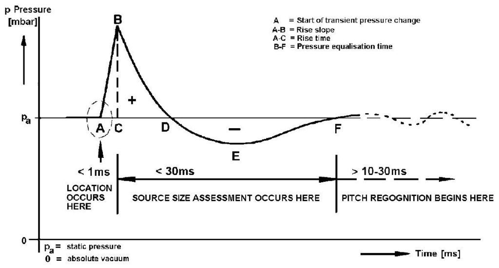
I like this graphic of an idealized transient pressure response. Not only is it about time coherency, but also what happens immediately after the transient or step in the case of our loudspeakers and room:
I modeled my step response so it measures similar at the listening position. Note the time scale. I need to take another measurement as I had a ground loop/RF buzz on this measurement, and a refection at 2.3ms, but the overall shape is similar:
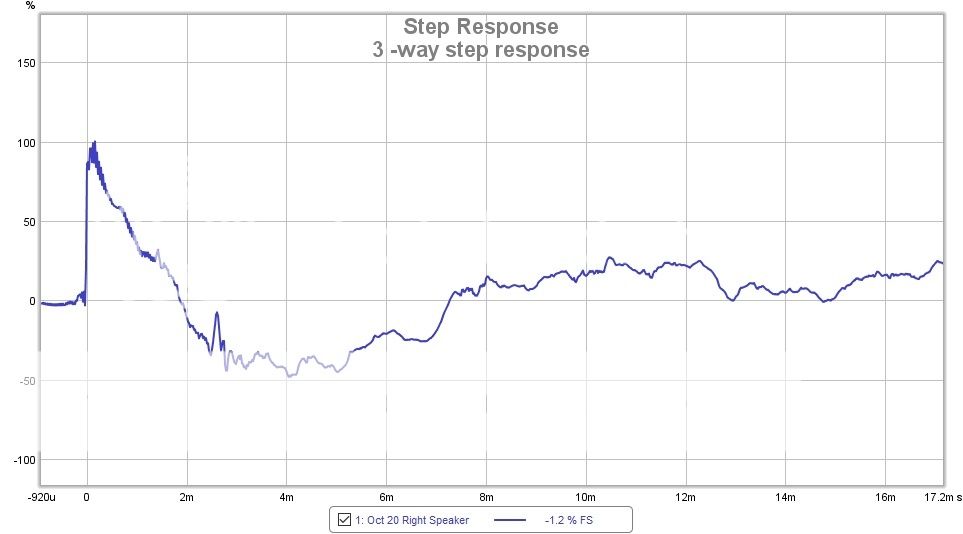
One aspect I found that affects the pressure equalization time is how quickly the woofer stops after the impulse has been sent through. Incorporating a subsonic HP filter, in my case, really changed the pressure equalization time. I found it also reduced the Group Delay. Something to consider if one hasn't played with subsonic filters between 15 and 20 Hz.
I modeled my step response so it measures similar at the listening position. Note the time scale. I need to take another measurement as I had a ground loop/RF buzz on this measurement, and a refection at 2.3ms, but the overall shape is similar:
One aspect I found that affects the pressure equalization time is how quickly the woofer stops after the impulse has been sent through. Incorporating a subsonic HP filter, in my case, really changed the pressure equalization time. I found it also reduced the Group Delay. Something to consider if one hasn't played with subsonic filters between 15 and 20 Hz.
ISTR commenting on this in the acourate group but the question in my mind is how much of that is just a measurement artefact of the sweep bandwidth vs the speaker (sub) bandwidth? i.e. it seems to me that the measurement is simply reflecting the presence of infrasonic content (assuming you have a sub that is capable of that) in the sweep hence there is no audible impact *unless* you are also playing infrasonic content (tends to mean films).One aspect I found that affects the pressure equalization time is how quickly the woofer stops after the impulse has been sent through. Incorporating a subsonic HP filter, in my case, really changed the pressure equalization time. I found it also reduced the Group Delay. Something to consider if one hasn't played with subsonic filters between 15 and 20 Hz.
I don't have subs and listen mostly to music. I can hear an audible difference when I AB filters with and without the subsonic filter in JRiver's convolution engine while listening to music. The subjective sense I get is a tighter impact and clarity in the bottom end, especially on drum impacts. After the transient impact, there is a sense of air, which I assume is the pressure equalization time. I have not formally performed an ABX test, but for folks using JRiver or other Convolution engine that can that switch filters in real time can easily test with a HP filter in and out of the signal path.
I like this graphic of an idealized transient pressure response. Not only is it about time coherency, but also what happens immediately after the transient or step in the case of our loudspeakers and room:
I modeled my step response so it measures similar at the listening position. Note the time scale. I need to take another measurement as I had a ground loop/RF buzz on this measurement, and a refection at 2.3ms, but the overall shape is similar:
One aspect I found that affects the pressure equalization time is how quickly the woofer stops after the impulse has been sent through. Incorporating a subsonic HP filter, in my case, really changed the pressure equalization time. I found it also reduced the Group Delay. Something to consider if one hasn't played with subsonic filters between 15 and 20 Hz.
Without wanting to turn this discussion into a "my STEP is larger/longer than yours" the shape and the size of the step is largely determined by the shape of the FR response and its roll of on either side. (and anything that happens in between that could turn the phase like crossovers do)
My step shape largely agrees with the one posted by Mitch:
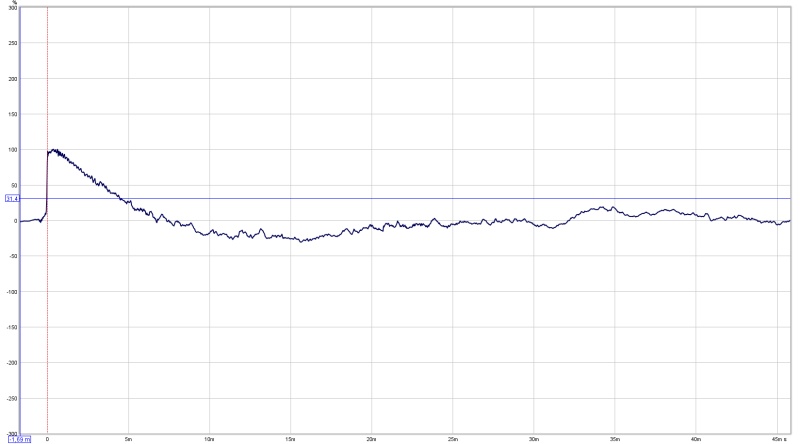
Note the difference in window length, my window is 45 ms, Mitch's is 17 ms.
My STEP stays above zero for a longer amount of time, meaning I have more output down low with minimum phase still closely following the frequency response before reaching the roll off that I set (to protect my drivers, I do play movies and run no subs) which starts at about 30 Hz. The general shape is similar as we have similar room curves, but I suspect the phase from Mitch is deviating from flat (or actually minimum phase behaviour) a bit sooner than mine, hence the shorter time above the zero line. An APL_TDA measurement could confirm or show that. But a simple FR and phase plot would too.
Every change in the FR shape changes the STEP shape too. See how my step climbs a little on the very top end? That's because it drops off earlier than Mitch's tweeter does.
I have a lot of other examples, one which flies high until crossing zero at ~15 ms. That is a correction with linear phase and flat frequency response as if I didn't have a rolled off frequency response anywhere. It doesn't make it sound any better though. I've tried lot's of things and the best sounding one for me was the STEP I got when the phase plot tracks the calculated minimum phase response of the frequency curve as close as possible. In other words as if I had a huge full range driver that has ideal minimum phase behaviour over it's entire usable bandwidth. It worked better than no group delay at all to 20 Hz while still having a rolled off low frequency response at 30 Hz.

Light red is mine, dark red is Mitch.
So the above linked "ideal" graph isn't telling me much about the true ideal transient STEP response shape. It's kind of limited in bandwidth to be honest on first glance.
Here's what a STEP of a 20 hz to 20 KHz looks like with flat phase and flat FR within that bandwidth:
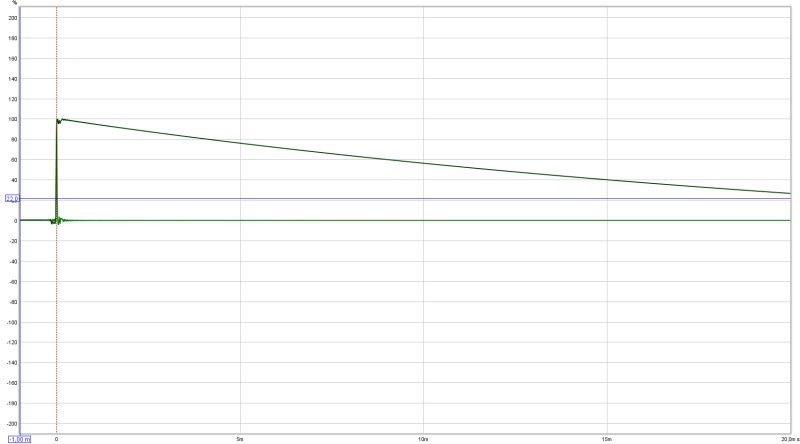
Still flying high in this 20 ms view...
It's the direct loop back of my DAC right back into the mic. input. So it's things like roll off and frequency shaping that largely determine the final shape of the STEP response. Nothing more, nothing less. Unless there is phase manipulation either by crossovers or with a linear phase correction applied or some other horrible stuff that we try to avoid 😀.
Last edited:
.....One aspect I found that affects the pressure equalization time is how quickly the woofer stops after the impulse has been sent through. Incorporating a subsonic HP filter, in my case, really changed the pressure equalization time. I found it also reduced the Group Delay. Something to consider if one hasn't played with subsonic filters between 15 and 20 Hz.
Thanks tip.
Have no science for below passive network on woofer do nearly the same so nothing other than own subjective listening tests. Think its the LCR network part that do the job so one can probably omit RC network parts R3/4 and C2/3 in systems where woofer duty is not contributing in mid band. Woofer stroke and oscillating low frq rumble from recordings is by visual inspection of woofer considerable less with such a network. Some components can be costly but high value capacitors works fine with good electrolytic type wired back to back. Blue trace is active network grey trace network bypassed.
Attachments

nicely illustrated & I think that's the point I was driving at. The scale required to show that "ideal step" is a function of the bandwidth of the system and so if the spectral content (of the content you listen to) is wide enough to stress your system then the question is whether the audible aspect is the removal of that stress or whether there is something else going on.
I haven't rigorously tested it (i.e. no blind tests or anything like that) but the tests I've done (comparing different linear phase high pass filters) indicated no audible difference but a fairly substantial measured difference in the SR. I do run with subs that are not stressed at those frequencies though.
I haven't rigorously tested it (i.e. no blind tests or anything like that) but the tests I've done (comparing different linear phase high pass filters) indicated no audible difference but a fairly substantial measured difference in the SR. I do run with subs that are not stressed at those frequencies though.
Even though I don't have subs, I do have the liberty to get my phase linear without changing SPL, in other words, adjust the group delay at those lower frequencies.
Purely subjective listening, I prefer the minimum phase tracking at those lower frequencies. It simply sounds more natural that way.

This APL plot shows the timing with my preferred minimum phase roll of closely following the frequency roll off. We are talking about a tiny change in group delay here. No driver stress involved. No change in the frequency curve, only in phase. It was one of the questions I asked Raimonds Skuruls: http://www.diyaudio.com/forums/full-range/284916-room-correction-speaker-correction-what-can-we-do-dsp-power-now-availabl.html#post4575780
Purely subjective listening, I prefer the minimum phase tracking at those lower frequencies. It simply sounds more natural that way.
This APL plot shows the timing with my preferred minimum phase roll of closely following the frequency roll off. We are talking about a tiny change in group delay here. No driver stress involved. No change in the frequency curve, only in phase. It was one of the questions I asked Raimonds Skuruls: http://www.diyaudio.com/forums/full-range/284916-room-correction-speaker-correction-what-can-we-do-dsp-power-now-availabl.html#post4575780
Last edited:
I'm not sure they are equivalent changes; i.e. one has a bandwidth change but the other doesn't, one is a move towards linear phase, the other remains minimum phase.
At least it would be helpful to separate the two effects anyway
At least it would be helpful to separate the two effects anyway
I'm not sure they are equivalent changes; i.e. one has a bandwidth change but the other doesn't, one is a move towards linear phase, the other remains minimum phase.
At least it would be helpful to separate the two effects anyway
They are not the same thing. Just sharing my thoughts/experience, as this is a thread on group delay.
(comparing different linear phase high pass filters)
Though this quote is more like my example, a linear phase high pass changes the FR, but not the phase. Basically the other way around 🙂.
I was talking about changing phase, and not the FR. Both options, either changing phase (without changing FR) or changing FR (without changing phase) will make it deviate from minimum phase behaviour, right?
Another post that touches on this subject: http://www.diyaudio.com/forums/multi-way/283068-mini-synergy-horn-experiment-27.html
Again, saying the measured phase should likely follow the derived minimum phase plot of the frequency curve.
The only reason I mention it is because programs like RePhase let you alter the phase without changing the SPL FR curve. After running my own tests I no longer think that is the way to go (to change the phase as if there was output all the way down to DC).
Judging the STEP response from Mitch I can't help but feel there's an earlier deviation in phase as it's simply too short (B to F) to be minimum phase over his complete bandwidth. Sorry Mitch, a simple phase plot can prove me wrong, include REW's calculated minimum phase.
Or better yet, measure the setup with APL_TDA (in trail/demo) and show the first 30 ms plot. 🙂
Last edited:
...
So the above linked "ideal" graph isn't telling me much about the true ideal transient STEP response shape. It's kind of limited in bandwidth to be honest on first glance.
That's actually my point 🙂 Speakers are not linear devices, certainly compared to the other digital and electrical devices in the signal chain, and my preference is bandwidth limited. And in the case of low frequencies, prevents excessive cone motion (i.e. unloading) at or below resonance regardless if one is running subs or not.
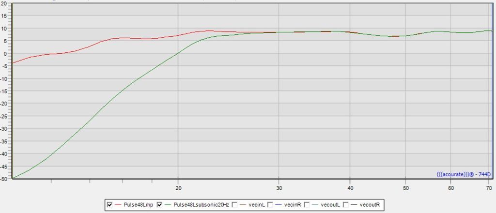
Here is a quick graphic of the simulated response at the LP with and without the 20 Hz subsonic filter.
An externally hosted image should be here but it was not working when we last tested it.
It's a considerable difference. The speakers I have can go quite deep and at the levels I listen to unstressed. The amplifiers I run directly to woofers have a reasonably high damping factor.
When I AB the two curves, I can clearly hear a difference in the bottom end regardless of the content played. My preference is for a much tighter impacting sound. The corresponding step response is inline with the idealized response referenced, if one is designing for a 20Hz to 20 kHz target. Others may prefer the sound of rumbling subsonics, but I don't find it very musical sounding. A certain mastering engineer on the Acourate forum went through the same exercise, with stereo subwoofers of high quality, and noted the audible difference as well and keeping the subsonic filter.
I didn't post this to start a debate, but rather as a potential solution to try and reduce group delay as a digital subsonic filter is simple to implement, test and listen to. However, it presumes that the subsonic filter used does not introduce delays of it's own.
But that subsonic linear phase filter would make it seem like the phase still tracks the FR that is extending further out below 20 Hz. Thus the phase isn't following minimum phase. Exactly my point.
Shorter group delay? Yes. But the phase isn't tracking the FR plot. That is exactly the same thing as I was posting about. But I do have a subsonic filter, but not a linear phase one. My phase turns away from flat over that last octave.
You're protecting the driver, also taking away possible rumble down low but in the process you "fake" the phase response to act as if that filter isn't there.
I used to think that was the way to go. I don't after trying both ways. My bottom end is still very much tight. Look at the graph.
I don't see this in your STEP, Mitch. It ends too soon. There has got to be something between 20 and 20 KHz that makes your phase turn somewhere. Not wrap, but turn away from following the frequency response.
Last edited:
yes sure.Though this quote is more like my example, a linear phase high pass changes the FR, but not the phase. Basically the other way around 🙂.
I was talking about changing phase, and not the FR. Both options, either changing phase (without changing FR) or changing FR (without changing phase) will make it deviate from minimum phase behaviour, right?
Now that I think about it some more, I've personally only compared an acourate correction with different linear phase HPFs vs with no HPF. However acourate itself targets a minimum phase response (at least it does to the best of my knowledge), i.e. you can elect to apply a subsonic filter which it implements using a linear phase HPF (it's a 2nd order NT IIRC) but that doesn't mean the final result is linear (or at least non minimum) phase as that HPF is folded into the final correction and is in scope of its excess phase correction (which targets a minimum phase response).
I probably need to review those results in more detail to be sure of what comes out in the end in my system though, on paper may not equal in practice after all.
- Status
- Not open for further replies.
- Home
- Loudspeakers
- Full Range
- Group Delay Questions and Analysis