[Light bulb going off] Of course! Since Group Delay is d(phase)/d(frequency), a linear phase system will have constant Group Delay because the derivative of a constant slope is a constant! And the steeper that (constant) slope, the higher the (constant) Group Delay! Wow!
Jan
Jan, a linear phase system will have group delay = 0. As soon as the phase curve has a slope, it is no longer linear phase.
However, it is mathematically possible to create filter with a slope for which the group delay is a constant, however, this will not be a system that can be built with physical filters. The reason is because group delay is calculated with Hz on a linear scale, whereas the physical reality deals with Hz on a log scale.
Group delay should for this reason be forgotten. It only obfuscates and does not provide any insight that cannot be better derived from other metrics.
Last edited:
Jan, a linear phase system will have group delay = 0. As soon as the phase curve has a slope, it is no longer linear phase.
However, it is mathematically possible to create filter with a slope for which the group delay is a constant, however, this will not be a system that can be built with physical filters. The reason is because group delay is calculated with Hz on a linear scale, whereas the physical reality deals with Hz on a log scale.
Group delay should for this reason be forgotten. It only obfuscates and does not provide any insight that cannot be better derived from other metrics.
What other metric do you suggest when it comes to evaluating time arrival?
Jim,
I would suggest impulse measurements to determine the acoustic center of drivers and phase diagrams to align filter slopes and xover points.
This is all you need.
As I mentioned before, I have done some measurements in a reverberant environment to illustrate why imo group delay is not useful. First the phase plot:

Which translates in the following plot for group delay

As you can see, it gets negative. It also clearly shows how the measurement gets distorted because 1 Hz is treated the same everywhere on the scale. Looking only at group delay, an 8th order filter at 1200 Hz would look better than a 2nd order filter at 80 Hz. This is clearly not in line with experimental results.
I find it a bit unfortunate that much of the research done by Blauert and others use group delay to determine audibility of what are essentially phase shifts. It makes their results so much more difficult to translate into what is relevant for engineering loudspeakers.
I would suggest impulse measurements to determine the acoustic center of drivers and phase diagrams to align filter slopes and xover points.
This is all you need.
As I mentioned before, I have done some measurements in a reverberant environment to illustrate why imo group delay is not useful. First the phase plot:

Which translates in the following plot for group delay

As you can see, it gets negative. It also clearly shows how the measurement gets distorted because 1 Hz is treated the same everywhere on the scale. Looking only at group delay, an 8th order filter at 1200 Hz would look better than a 2nd order filter at 80 Hz. This is clearly not in line with experimental results.
I find it a bit unfortunate that much of the research done by Blauert and others use group delay to determine audibility of what are essentially phase shifts. It makes their results so much more difficult to translate into what is relevant for engineering loudspeakers.
Last edited:
Jim,
I would suggest impulse measurements to determine the acoustic center of drivers and phase diagrams to align filter slopes and xover points.
This is all you need.
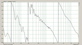
As I mentioned before, I have done some measurements in a reverberant environment to illustrate why imo group delay is not useful. First the phase plot:
View attachment 489793
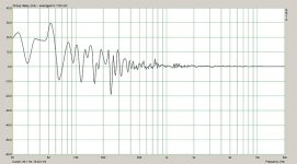
Which translates in the following plot for group delay
View attachment 489792
As you can see, it gets negative. It also clearly shows how the measurement gets distorted because 1 Hz is treated the same everywhere on the scale. Looking only at group delay, an 8th order filter at 1200 Hz would look better than a 2nd order filter at 80 Hz. This is clearly not in line with experimental results.
I find it a bit unfortunate that much of the research done by Blauert and others use group delay to determine audibility of what are essentially phase shifts. It makes their results so much more difficult to translate into what is relevant for engineering loudspeakers.
But the GD only turns negative because the phase shift turns back in some places. Isnt this just due to measurement or math ripple?
Jan
GD is the correct measure; when analysis is done correctly is correlates directly to what is seen in the impulse response.
Correct Jan, it is the reverberant environment which causes these wriggles. I show it to illustrate that group delay is just a phony measure. Between 50 and 65 Hz, the group delay changes from +30 to -10 ms.
In the real world, there absolutely is no 40 ms difference in measurable delay between these two frequencies. If anybody can tell me what is indicated by these group delay milliseconds, I will eat my hat and be your BFF.
In the real world, there absolutely is no 40 ms difference in measurable delay between these two frequencies. If anybody can tell me what is indicated by these group delay milliseconds, I will eat my hat and be your BFF.
GD is the correct measure; when analysis is done correctly is correlates directly to what is seen in the impulse response.
And it correlates equally well to what is seen on a phase plot.
Actually, phase plot is first derived from impulse response. GD is then calculated on the basis of the phase plot. There is no information provided by GD which is not in the phase plot already.
But the presentation is worse, it is just as unwieldy as a phase plot on linear paper would be.
Yes, working with phase plot is more direct when aligning drivers. When window is chosen for analysis, looking at GD with negative values reveal that window is too long and includes reflections.
phony=alias
No hats will be eaten.
phony=alias
No hats will be eaten.
and be your BFF.
I don't know what it is but it sounds quite frightening!
In answer to the bolded area, it this to say that REW sweeps should always start below 20hz as to not induce frequency ripple? (when analyzing low frequency GD).
Is the default settings in REW sufficient to capture the high pass filter behavior of the IR? (those settings besides the sweep frequency which is addressed above) ? For instance the gate settings (left and right window lengths) ?
As for the rest, I thank you for a very thorough response. But I am not sure I am getting your intended point. Is there a conclusion you draw as to GD accuracy based on sweep frequency width? I see your "ripple" pic.
Is what your saying as simple as; Sweep lengths that begin 20hz or above are subject to "frequency ripple", making GD measurements less accurate. And I guess the further you are from 20hz, the bigger the ripple?
For measurements you are pursuing, REW windowing should have symmetrical left and right windows. Blackman, Blacmman-Harris 4 term, Blackman-Harris 7 term windows are your best friends forever. These have little ripple in passband and stopband with relatively well behaved attenuation bands. With sweeps generated starting >19Hz in REW, the left hand window captures the FIR filter and generates correct GD result of zero for the FIR component of the resulting IR captured with such sweeps.
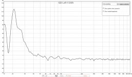
View attachment 489827
(Measured at the LP)
Here is my 1/24th GD. I dont have all those huge time wiggles like yours. It did take a lot of work with PEQ filters to get the wiggles out though.
Is it possible that your fluctuations are room reflections? Not a shortcoming of the GD measurement?
Exactly. PEQ filters matched to room modes for listening position mitigate GD observed at listening position for the corrected frequencies, but making direct sound of speakers far from flat.
View attachment 489827
(Measured at the LP)
Here is my 1/24th GD. I dont have all those huge time wiggles like yours. It did take a lot of work with PEQ filters to get the wiggles out though.
Is it possible that your fluctuations are room reflections? Not a shortcoming of the GD measurement?
You are correct, I used a bad measurement, but not an impossible one. In this case the cause was indeed room reflections, but you might also encounter loudspeakers something like this. I just used a bad measurement to make the following point: group delay says nothing about the arrival time of frequency components vis a vis each other. It can go from very large positive to pretty negative in a 15 Hz span. The milliseconds group delay is denoted in is not something that directly relates to reality, it is a mathematical construct, literally a derivative.
The only use for it is if you are interested in the rate of change of the phase at a certain frequency, but even there it is flawed for audio, because it uses a linear scale where a log scale would have been appropriate.
In short, what I am trying to communicate is that for designing speakers, the use of group delay as a concept can only lead to confusion and wrong conclusions. You can get more insight by looking at the impulse and phase plots.
Last edited:
Exactly. PEQ filters matched to room modes for listening position mitigate GD observed at listening position for the corrected frequencies, but making direct sound of speakers far from flat.
By direct sound, what measure do you mean?
You are correct, I used a bad measurement, but not an impossible one. In this case the cause was indeed room reflections, but you might also encounter loudspeakers something like this. I just used a bad measurement to make the following point: group delay says nothing about the arrival time of frequency components vis a vis each other. It can go from very large positive to pretty negative in a 15 Hz span. The milliseconds group delay is denoted in is not something that directly relates to reality, it is a mathematical construct, literally a derivative.
The only use for it is if you are interested in the rate of change of the phase at a certain frequency, but even there it is flawed for audio, because it uses a linear scale where a log scale would be appropriate.
In short, what I am trying to communicate is that for designing speakers, the use of group delay as a concept can only lead to confusion and wrong conclusions. You can get more insight by looking at the impulse and phase plots.
You do realize that in my case, and the threads case, I am not measuring the loudspeaker per say, but at the LP.
Last edited:
Jan, the exact content of the B and the Fs will be determined at a later stage, but there is a wide range of possibilities.
By direct sound, what measure do you mean?
Sound that travels reflection free directly from speaker to microphone.
Sound that travels reflection free directly from speaker to microphone.
I know what the definition is 🙄
What measurement tool do you mean. FR? Gated FR?
In other words, if you wanted to see if all your PEQ adjustments were affecting the direct response, where would you look?
My standard FR looks fine.
Jim, I hope you're still getting notifications for this thread, We were introduced to a tool recently, that would have been quite a big help in this quest you had at the time of this thread.
http://www.diyaudio.com/forums/full-range/284916-room-correction-speaker-correction-what-can-we-do-dsp-power-now-availabl.html
Read the last paper, linked in the first post. The visual examples are probably all you need to look at to see my point. This tool, APL_TDA lets you see the exact timing of your speakers in the room. The Demo version is enough to show you the plots. You can't save them but it's a real nice way to see what's going on with that first wave front hitting your listening position. It will also show you a group delay plot, but the visual presentation of the enhanced wavelet view, in 2D or 3D is actually quite clear upon first sight of the graph.
Just thought I'd mention it.
- Status
- Not open for further replies.
- Home
- Loudspeakers
- Full Range
- Group Delay Questions and Analysis
