To add to this, it was obvious the 2 cycle had the most bass energy compared to the higher cycles of correction. As it is a tendency over a wide frequency area it really makes a difference in listening. Different targets would help even that playing field.
On a thread with Bob Katz about Audiolense he mentioned very small differences in db can be heard if that difference is over a wide frequency area. I tend to believe that.
On a thread with Bob Katz about Audiolense he mentioned very small differences in db can be heard if that difference is over a wide frequency area. I tend to believe that.
jim1961,
Thanks again for sharing. The playback of many tracks will seem to lose some dynamics as the correction strength increases, and without a perfect reference system for comparison, it can take a while to understand what's really happening. My thinking is that as any speaker/room resonances are excited by the signal, the extra energy adds to the sound dynamically and harmonically. In other words, the sonic elements that are de-emphasized with the correction in place may not actually be part of the recording. Of course, there are different philosophies regarding this subject and many people seem to enjoy or even prefer a system with at least a little bit of this coloration. I'm still willing to believe that if you were to listen for a while to all of your music corrected over 3-4 cycles, you might develop stronger feelings about it.
This relates to what X said as well. Psycho-acoustically, we need room ques (room reflections) to feel comfortable. These ques tell us not only we are in a room, but a sense of its dimensions and ambiance.
People dont mix or master in anechoic chambers for a reason.
This said, reflections alter the FR. If DRC is trying to correct out the effect of these reflections, it may very well also be diminishing our room ques.
Said another way, removing room effects entirely would be like listening in an anechoic environment.
X is right that I reintroduce 25-28ms delayed reflections purposely back to the LP. What I dont know is whether DRC is trying to affect these.
Might be interesting to look at corrected vs uncorrected plots limited to >20ms and see.
Edit: I think what we want DRC to do is remove/augment the early (<10ms - 15ms) reflection/room effects without altering the later ones.
Last edited:
Edit: I think what we want DRC to do is remove/augment the early (<10ms - 15ms) reflection/room effects without altering the later ones.
That's largely what the windowing is about. It shouldn't effect the later response too much as it corrects over a very short window.
The Normal template, which is 10 cycles has a window of 500 ms at 20 Hz and it tapers to 0.50 ms at 20 kHz. At 100 Hz that would be a 100 ms window and at 1 KHz it would only be 10 ms long. So the correcting should already be done by the time your signal hits the kicker. But, it will be different from an uncorrected signal and thus the kicker will reflect something different too.
Those windows mentioned (Normal template) are way longer than anything applied in your corrected test songs.
Out of curiosity, is it possible to apply different windowing to different parts of the spectrum.
Say,
4 cycles 20-100
3 cycles to 100-1k
2 cycles to 1k and up
Or only to the low end?
Not entirely like that but close enough...
You can do quite a few different things with windowing... More later, gotto run!
You can do quite a few different things with windowing... More later, gotto run!
OK I'm back...
You can define a time at 20 HZ and a time at 20 kHz. It does not need to be an exact number of cycles. Further more you have control over the slope which is used to get the time windowing in between. Look at this graph:
So you can further change the window at the mid frequencies by changing that value.
What you are describing would take a 4 cycle at 20 Hz and 2 cycle at 20 kHz and WE =1.0 to come closest to your proposal. I noticed I'm most sensitive to what it does for mid frequencies and have longer windows at the bottom and on top (my WE is ~0.89).
When running the controls yourself you can easily find the limits. But there are a lot more variables to play with as well. Lot's of choices to be made. A little change can go a long way here...
You can define a time at 20 HZ and a time at 20 kHz. It does not need to be an exact number of cycles. Further more you have control over the slope which is used to get the time windowing in between. Look at this graph:
The straight line like I described from the normal template would be WE (Window Exponent) = 1.0An externally hosted image should be here but it was not working when we last tested it.
So you can further change the window at the mid frequencies by changing that value.
What you are describing would take a 4 cycle at 20 Hz and 2 cycle at 20 kHz and WE =1.0 to come closest to your proposal. I noticed I'm most sensitive to what it does for mid frequencies and have longer windows at the bottom and on top (my WE is ~0.89).
When running the controls yourself you can easily find the limits. But there are a lot more variables to play with as well. Lot's of choices to be made. A little change can go a long way here...
Last edited:

For understanding sake, what does it really mean to be +90 at 200hz, or +360 degrees at 32hz?
Last edited:
If FR is flat, phase is flat, and waveform fidelity is perfect.
bwaslo:
Please show a real counter example.
Um. Pretty much every flat multiway speaker in the world, excepting maybe Quad ESL63, some Danleys, and a few others that are waveform compatible only on a fixed axis. Multiway speakers are generally all-pass (phase NOT tracking magnitude), not minimum-phase (phase calculateable from magnitude shape). Just take a microphone and a square wave generator to your speaker (assuming multiway and not one of the above mentioned) and see what you get. Even if you use a parametric equalizer to flatten it. If you get it to look remotely squarish over more than maybe a third octave (if at all), that would be exceptional (and worth showing!).
A lot of us hifi techies sometimes just assume that as things get more accurate or ideal they should sound more convincing, but I'm beginning to think that the correlation is kind of thin. Since the idea is to basically trick our minds into perceiving an illusory image, it may well be the case that some things less accurate might do the job better (listener dependent, probably). For instance, I can see the dots on my display screen (or lines on an old CRT TV, for you people old enough to remember that) a lot more accurately with my face a few inches from the screen. But the image is a lot better when I look from further back and when normal room lighting is included.Jim1961 said:Without DRC, the sound is a little more raw, but also more robust. More convincing (IMO). A better sense of being there
Last edited:
If FR is flat, phase is flat, and waveform fidelity is perfect. Please show a real counter example.
Look into the subject of all-pass filters. Without inductors an active circuit is necessary, but with inductors,
passive all-pass circuits can be designed, including for speaker system passive crossover networks.
Last edited:
I have taken microphone and square wave signal to various speakers I have implemented.
Attached is recording of swept square wave from about 80-3000Hz over period of about a 2 seconds; I've renamed it from .wav to .asc for upload. Just change extension back to .wav; open it up in a wave editor and you will see recognizable square wave form across entire interval.
Recording was produced during this experiment:
http://www.diyaudio.com/forums/multi-way/269936-cardioid-sum-monopole-dipole-speakers.html
Attachments
For understanding sake, what does it really mean to be +90 at 200hz, or +360 degrees at 32hz?
I guess no one bothered to answer this. You might have it figured out already.
If the phase is flat, at zero degrees it would mean all the frequencies arrive at the microphone without delay. So the phase rotation you are seeing, with a flat frequency response means 200 Hz arrives later than the frequencies before it.
It will even be later at 32 Hz due to more phase rotation measured.
Flat frequency plus flat phase could be considered time coherent. Look at my plot, gated 5 ms before first mayor reflections:

Measured at the listening spot, 3 meters away from the speaker.
I still need to work on the bottom end to get that into shape. That means fighting the room as well as the delays in the speaker itself.
You start with a speaker with crossovers that cause a certain amount of phase rotation. To get that phase plot flat would be do-able
by actively crossing the separate drivers with linear phase crossover filters. Each powered with their own amplifier. There are other ways
of coarse but it's never really simple without additional processing.
RePhase might get you there, mimicking the phase behavior of your crossovers and adjusting it to linear phase and that way giving you a flat phase response.
Your speakers behave excellent and so does your room. It might be worth a shot...
Last edited:

I understand phase relates to time. What I am trying to understand better is what the degree variation means in more absolute terms. In the graph shown are the phase plots of some different peoples mdat's that I have saved. Notice the scale (-2000 to +2000 degrees).
As you can see, most of these have more than a 4000 degree swing from top to bottom.
What I have noticed looking more closely at these different mdats is that all these except the green plot (mine) have significant mid and high frequency reflections. What seems to be happening is the phase plot averages in the reflection delays. So what your really seeing here is not the phase of the direct response of the speaker only, but rather some kind of hybrid phase response that includes the rooms delayed reflections.
So in order to have a flat phase as measured at the LP (ungated), one would have to remove all significant reflections?
I saw you that you gated your plot to 5ms to eliminate reflections. Thats kind of cheating isnt it?
Last edited:
That's not cheating for me... it is called dealing with the reality of a live living room 🙂.
You are absolutely correct in that observation, your plot of the left or right channel by itself shows phase wraps too if you don't gate before the kicker.
To get the phase of the speaker and nothing but the speaker would require access to an anechoic room. Your room comes close in the first few ms.
I want the early wave front to have good phase response. So looking at the gated response I can check it out. 5 ms is enough time to complete 50 cycles at 10 kHz but only 5 cycles at 1 kHz. So I adjust gating and browse trough the frequencies of interest.
Your chosen path is a very good approach but I cannot do that with my family living room. But would a band playing in my house not sound live? It should sound better in your room. I'm just dealing with my own reality. But feel free to gate and observe your phase. The gating won't make it flat. So it really isn't cheating...
My observation was that an ungated phase plot mdat at the LP doesnt show true phase or timing.
I think your response verifies that you agree with me.
By cheating, I only meant that a gated response doesnt mirror the phase or timing your actually going to hear at the LP.
What I think your saying is that your wanting to single out the direct response, via gating, and the timing your wanting to correct or look at is the direct only.
Very true... that's my view on things anyway. Get the first wave front correct.
Gating to look for it is a way of viewing that. Lots of things can cause phase wrap.
Look at my thread and you'll see my wiring caused it until I changed out the wires to another kind. A resonance in the speaker could cause it. It's not only reflections.
But you said a while ago you wanted to have a clear first 2-=25 ms time window, without reflections. Now you have to ask yourself if you wouldn't also like to have the waves hit you at the same time in that 25 ms time frame 😀.
Very true... that's my view on things anyway. Get the first wave front correct.
Gating to look for it is a way of viewing that. Lots of things can cause phase wrap.
Look at my thread and you'll see my wiring caused it until I changed out the wires to another kind. A resonance in the speaker could cause it. It's not only reflections.
But you said a while ago you wanted to have a clear first 2-=25 ms time window, without reflections. Now you have to ask yourself if you wouldn't also like to have the waves hit you at the same time in that 25 ms time frame 😀.
I would indeed.

So, how do I need to set these windows to see it that way?
0=left 20=right ???
In your measurement in REW on the SPL and Phase tap, click on the IR windows button above it and adjust the "Right Window" length.
Left Window is what happens before the impulse, Right Window is what happens after the impulse.
If you want to see what the room is adding, well sort of... you could set Window Ref Time to 20 ms and Right Window to 500, Left Window to 0. That would kinda relate to the power response in your room (basically what happens after the first 20 ms).
It would still have the original bass though as the wave length there is more than 20 ms.
20 ms is about one cycle at 50 Hz.

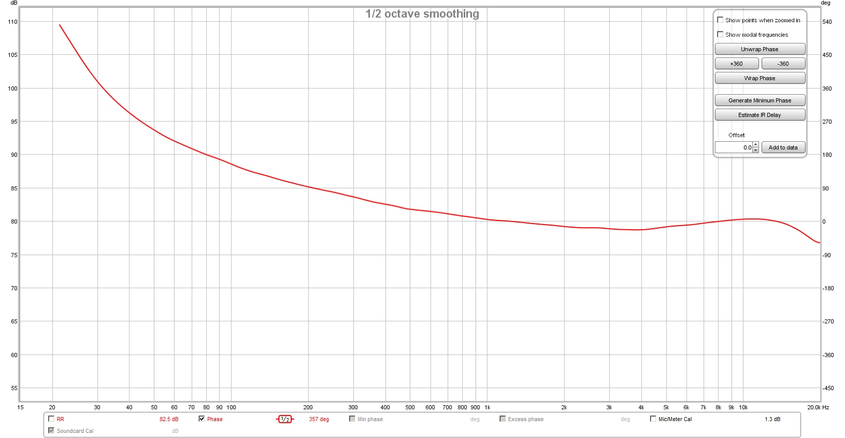
Setting the left IR to 0, and the right to 20ms, I get this. From 1K up, things seem pretty flat.
Below 1K, the upswing I suppose is inevitable.
I usually leave the left at 125, in my case with FIR filtering there is stuff happening there to influence the phase in total.
Sadly, I don't have a 20 ms reflection free window 🙂.
Your phase seems excellent for a multi way with crossovers. But it does show you not all sound is arriving at the same time. The 90 degree at 200 Hz seems a reality.
Sadly, I don't have a 20 ms reflection free window 🙂.
Your phase seems excellent for a multi way with crossovers. But it does show you not all sound is arriving at the same time. The 90 degree at 200 Hz seems a reality.
I usually leave the left at 125, in my case with FIR filtering there is stuff happening there to influence the phase in total.
Sadly, I don't have a 20 ms reflection free window 🙂.
Your phase seems excellent for a multi way with crossovers. But it does show you not all sound is arriving at the same time. The 90 degree at 200 Hz seems a reality.
It seems neither of us can have everything 🙂
- Status
- Not open for further replies.
- Home
- Loudspeakers
- Full Range
- Group Delay Questions and Analysis