Thanks for pointing that out...The VR1/VR2 components are in fact mounted in the thicker trace holes. Ugh!
I hope I didn't blow anything!
I'll fix that then do some measuring.
J1-J4 are tinned, yes...
Sent from my SM-G900W8 using Tapatalk
I hope I didn't blow anything!
I'll fix that then do some measuring.
J1-J4 are tinned, yes...
Sent from my SM-G900W8 using Tapatalk
Alas...I destroyed one of the 329's trying to desolder it 🙁
Project on hold....
Sent from my SM-G900W8 using Tapatalk
Project on hold....
Sent from my SM-G900W8 using Tapatalk
got the parts, repaired my mess up and we're up and running!
Thanks so much for the help everyone!
Looking at the output, it's a bit hotter than spec...
Sent from my SM-G900W8 using Tapatalk
Thanks so much for the help everyone!
Looking at the output, it's a bit hotter than spec...
Sent from my SM-G900W8 using Tapatalk


I have another question...and I appreciate the help as I am pretty much an electronics novice...
I have a dual winding transformer...outputs 2X24V
I just connect these to the input side of the SSR03...?
Schematic shows + and - inputs, but AC isn't +or-...?
I'm a bit confused :S
TIA
Edit: Damn...I have bigger issues. Regulator isn't working! I have to go thru and check everything, one component at a time...
The only thing that jumps out at me is DZ1/DZ2 components...I substituted blue LED's for these, instead of zeners...
You realise you need rectifiers and stuff to turn that AC into DC for the regulator?
jan
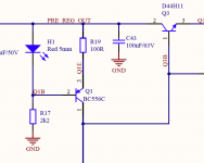
Look closely at the input side of the regulator....see those blocking diodes and capacitors....? They are rectifying the AC input...You realise you need rectifiers and stuff to turn that AC into DC for the regulator?
jan
Output is DC
Notice the setting on the multimeter.
Sent from my SM-G900W8 using Tapatalk
An externally hosted image should be here but it was not working when we last tested it.
Powered up and playing!!!
And sounding fantastic!
Sent from my SM-G900W8 using Tapatalk
Notice that blue LED's increases the the idle current and also increases the dropout voltage. It's possible that you must do some adjustments if you use LM317/337. There drawbacks to use blue or white LED's. I'll recommend red LED's.
That is what I am seeing in my setup...a slightly higher idle V.
What do you mean by dropout voltage?
I was under the impression the LED's were simply passive components, used to indicate V+ and V- operation.
I think I have some red LEDs laying around...
Sent from my SM-G900W8 using Tapatalk
What do you mean by dropout voltage?
I was under the impression the LED's were simply passive components, used to indicate V+ and V- operation.
I think I have some red LEDs laying around...
Sent from my SM-G900W8 using Tapatalk
Dropout voltage is the minimum voltage across the regulator in order to work properly. Is is defined as VbeQ3 + Vled- VbeQ1 You see that choice of LED will have a directly influence of dropout voltage.
The LED serves as a low voltage zener setting the bias for the Q1. IQ1 = (Vled-VbeQ1)/R19
The LED serves as a low voltage zener setting the bias for the Q1. IQ1 = (Vled-VbeQ1)/R19
Attachments
Thanks for the explanation PA.
Will it be okay to use until I get the proper LEDs installed, despite the slightly higher idle V?
Sent from my SM-G900W8 using Tapatalk
Will it be okay to use until I get the proper LEDs installed, despite the slightly higher idle V?
Sent from my SM-G900W8 using Tapatalk
Any interest for a third run? I prepare the wiki page so we will see the interest.
Sign up in the wiki page if you are interested. It's no comment yet. If you have problems with editing the wiki, send me a message and I'll fix that.
Sign up in the wiki page if you are interested. It's no comment yet. If you have problems with editing the wiki, send me a message and I'll fix that.
Last edited:
Guys, sign the wikilist with the exact amount you want. PH and MisterRogers on the list so far.
- Home
- Group Buys
- Group Buy: SSR03 Super Regulator Power Supply