still not able to source the 556...
Looking at a NTE159
Specs are:
BIPOLAR TRANSISTOR, PNP, -80V TO-92
BIPOLAR TRANSISTOR, PNP, -80V TO-92; Transistor Polarity😛NP; Collector Emitter Voltage V(br)ceo:80V; Power Dissipation Pd:625mW; DC Collector Current:-800mA; DC Current Gain hFE:250; Operating Temperature Min:-55°C; No. of Pins:3 ;RoHS Compliant: Yes
This should work fine, no...?
I have another question...and I appreciate the help as I am pretty much an electronics novice...
I have a dual winding transformer...outputs 2X24V
I just connect these to the input side of the SSR03...?
Schematic shows + and - inputs, but AC isn't +or-...?
I'm a bit confused :S
TIA
Edit: Damn...I have bigger issues. Regulator isn't working! I have to go thru and check everything, one component at a time...
The only thing that jumps out at me is DZ1/DZ2 components...I substituted blue LED's for these, instead of zeners...
Last edited:
I think I see the problem...and I think it's the DZ diodes.
In this image of yours, DZ1/DZ2 are soldered on the outer solder holes, whereas my LED's are soldered on the INNER solder holes, directly underneath the diodes in this pic...
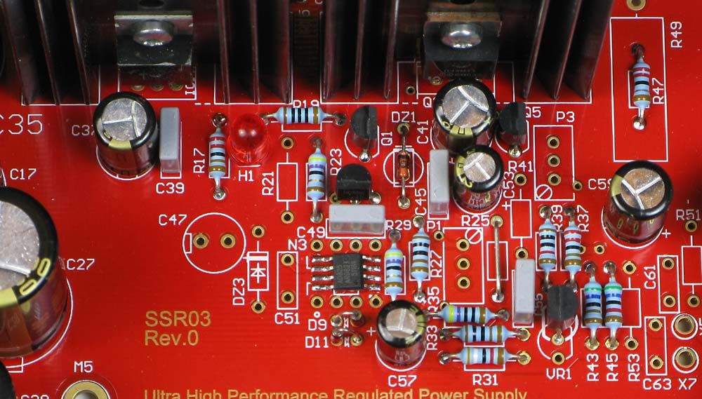
Edit: But I see the inner and outer holes use the same traces...so that isn't it (and polarity looks good)
I'm measuring very low DC current at the bigger capacitors...?
Getting power thru the unit now, however...
Negative side is outputting -0.6VDC and positive side, with my meter set to the "20DC" scale, it runs off the scale! At the "500VDC" setting, it's reading 033VDC...(330VDC!?)
The red LED on the neg side is illuminated properly, however, on the pos side, it is very dim...
Also, if I just connect just one side of the input, AC1 for example, I get output on both sides, -Uout and +Uout (and the same VDC as mentioned above)
Switching input to AC2, it's exactly the same. Connecting both AC1 and AC2, again, exact same output on both - and +
DZ1/DZ2 LED's don't light up...
PA...have any ideas...?
TIA
Last edited:
The pcb will take two windings or a center tap transformer. Secondary winding 1 goes to X1, pin 1 and 2. Winding 2 to X1, pin 3 and 4. Here is the polarity of the windings important. The dot marked wire of winding 1 goes to X1, pin 1 and for winding 2 X1, pin 3
Which BOM have you used? Voltage, used reference? AC voltage? How much?
EDIT: 24 VAC, LM431 and 15 V, according to posts above.
You are mentioning about a LED instead of DZ1? Why? It won't work I might add. I suggest that you use my BOM to start with.
Which BOM have you used? Voltage, used reference? AC voltage? How much?
EDIT: 24 VAC, LM431 and 15 V, according to posts above.
You are mentioning about a LED instead of DZ1? Why? It won't work I might add. I suggest that you use my BOM to start with.
Last edited:
Thanks for the reply...
I went with LM329 (15V) instead, for the lower part count....
Input voltage is 28VAC (due to my higher household V)
I used LED's for DZ1/2 because your BOM says diode "or a LED", and I already had a selection of LED's.
As for my transformer, here is what it has for input/output. I think it is not center tapped...
I connected it to X1, from left-right (can't see PIN numbers) red-blk, grey-org.
An externally hosted image should be here but it was not working when we last tested it.
It's a bit unclear, the part number goes to a zener which it should be. I will change the description text. The text is for the default part which is zener/LED.
If you check the schematics you will see that AC1 corresponds to pin 1 on the X1 terminal.
If you check the schematics you will see that AC1 corresponds to pin 1 on the X1 terminal.
Last edited:
Wungun,
download the datasheet for the toroid... don't know whether there are any markings. Connect your primary windings according to your mains voltage. Connect the secondary windings to X1 and X2 (i.e. black-red and orange-grey).
Exchange the LED's for the proper zeners (the text in the BOM is indeed a bit misleading but there is no 6.8V LED...) and test again.
Connect the transformer this way:
AC1 Black
GND Red
GND Orange
AC2 Grey
Pay attention also how you shall connect the primary windings.
If you have turned the LED in DZ1/DZ2 position right it should work although the output of the opamp will be very unoptimal. You should have the output at the half of the supply voltage of the opamp.
Thanks for the reply...I have the proper zeners on order...
I'm hoping this is the issue...I'll be pulling my hair out trying to figure out if it's anything else!
Sent from my SM-G900W8 using Tapatalk
I'm hoping this is the issue...I'll be pulling my hair out trying to figure out if it's anything else!
Sent from my SM-G900W8 using Tapatalk
Have you mounted the LED in the right direction? Cathode (flat side) shall be in the opposite direction compared to the zener.
What is your problem really? Is it 33 V out?
What is your problem really? Is it 33 V out?
Anode of the led is soldered to the + pin on the board. This is incorrect?
Negative output is measuring -0.6V, positive side I think is 33v (goes off the scale on my meter set to "20v range", which to me says the voltage is in the triple digit range...?
Sent from my SM-G900W8 using Tapatalk
Negative output is measuring -0.6V, positive side I think is 33v (goes off the scale on my meter set to "20v range", which to me says the voltage is in the triple digit range...?
Sent from my SM-G900W8 using Tapatalk
If you use the LM329, it must be mounted in the thin outline of the VR1 and VR2. Is that the case?
Voltage at pin 3 IC1 and pin 2, IC2?
Are the sense inputs connected somewhere? Put a tin blob on J1-J4.
Can you measure the voltage on pin 2, 3, 6, and 7 on N1/N3 and pin 2, 3 , 4 and 6 N2/N4?
Voltage at pin 3 IC1 and pin 2, IC2?
Are the sense inputs connected somewhere? Put a tin blob on J1-J4.
Can you measure the voltage on pin 2, 3, 6, and 7 on N1/N3 and pin 2, 3 , 4 and 6 N2/N4?
- Home
- Group Buys
- Group Buy: SSR03 Super Regulator Power Supply