Greg Stewart x2
ppap64 x 2 V2
Peterma x 3 V2
kenlaumm x 2 V2
j.burtt x 2
crowlie x3 V2
ed linssen x2 V2
mravinsky x2 V2
palmito x2 V2
xaled x2 V2
noizas x4 V2
wlowes 1x V2
pchw 2x V2
ppap64 x 2 V2
Peterma x 3 V2
kenlaumm x 2 V2
j.burtt x 2
crowlie x3 V2
ed linssen x2 V2
mravinsky x2 V2
palmito x2 V2
xaled x2 V2
noizas x4 V2
wlowes 1x V2
pchw 2x V2
Greg Stewart x2
ppap64 x 2 V2
Peterma x 3 V2
kenlaumm x 2 V2
j.burtt x 2
crowlie x3 V2
ed linssen x2 V2
mravinsky x2 V2
palmito x2 V2
xaled x2 V2
noizas x4 V2
wlowes 1x V2
pchw 2x V2
badrisuper X 1
ppap64 x 2 V2
Peterma x 3 V2
kenlaumm x 2 V2
j.burtt x 2
crowlie x3 V2
ed linssen x2 V2
mravinsky x2 V2
palmito x2 V2
xaled x2 V2
noizas x4 V2
wlowes 1x V2
pchw 2x V2
badrisuper X 1
Greg Stewart x2
ppap64 x 2 V2
Peterma x 3 V2
kenlaumm x 2 V2
j.burtt x 2
crowlie x3 V2
ed linssen x2 V2
mravinsky x2 V2
palmito x2 V2
xaled x2 V2
noizas x4 V2
wlowes 1x V2
pchw 2x V2
badrisuper X 1
tagheuer x2
ppap64 x 2 V2
Peterma x 3 V2
kenlaumm x 2 V2
j.burtt x 2
crowlie x3 V2
ed linssen x2 V2
mravinsky x2 V2
palmito x2 V2
xaled x2 V2
noizas x4 V2
wlowes 1x V2
pchw 2x V2
badrisuper X 1
tagheuer x2
Very nice Ryan. Wish I hadn't bought the V1 boards. Lol. Layout is much more ideal
over V1. Btw should consider regulators on the pcb as well. .
Thanks,
It did cross my mind about the regs on board, see how I go, might be able to put a test circuit on the test pcb.
I am using the classic version and no regrets. Will I upgrade to the V2? Absolutely as a 4 layer design with I2S attenuation will give that reference design edge. It will also be more expensive to fabricate, and a bunch more tiny little parts to solder.
Likely the classic (V1) is more than enough for most systems. I will likely list mine in the swap meet for anyone wanting a fast and cost effective TDA.
Great work Ryanj.
Thanks for your support in these projects Walter, definitely nothing bad about the sound V1 is producing for me aswell, stunning actually. V2 should give a fair bit more for people with a system that can reproduce a higher fidelity. Although having said that, the improvements I can hear are not only that of apparent resolution, but imaging (especially height) has improved by a substantial amount. Bass is also much easier to follow.
Electro cap size - no problem, ill put that into the design. 5mm pitch?
Thanks,
It did cross my mind about the regs on board, see how I go, might be able to put a test circuit on the test pcb.
Hi Ryan, I would be interested in on board power supplies as well. It would make it bigger and increase cost, but the whole idea of removing long wires etc seems appealing. But then I guess we get into the whole what reg to use and then appeal may not be there for those who don't want those regs. I wonder if its feasible to have a break away board for those that don't want the regs?
Not demands just ideas🙂
It is always good to have the regulators as close as posible to the dac. For those who
wants to use their own recipe, it's very easy to jumper their regs onto the boards.
cheers
wants to use their own recipe, it's very easy to jumper their regs onto the boards.
cheers
Concerning integrated PSU
Hi,
Distance between regulator and the load is really sensitive issue, especially in case of shunt regulator.
It would be nice to have such PCB if shunt regulator would be like Salas designed.
But this would be completely another PCB because of bigger size and I doubt it would be reasonable because V2 is going to be 4 layer PCB.
Hi Ryan, I would be interested in on board power supplies as well. It would make it bigger and increase cost, but the whole idea of removing long wires etc seems appealing. But then I guess we get into the whole what reg to use and then appeal may not be there for those who don't want those regs. I wonder if its feasible to have a break away board for those that don't want the regs?
Not demands just ideas🙂
Hi,
Distance between regulator and the load is really sensitive issue, especially in case of shunt regulator.
It would be nice to have such PCB if shunt regulator would be like Salas designed.
But this would be completely another PCB because of bigger size and I doubt it would be reasonable because V2 is going to be 4 layer PCB.
Yep regulator war is gonna start as there's just too many choices.
From my pass experience a properly implemented TL431 shunt
is more then sufficient for the TDA. I may be flame for saying this
but the low z & wide band doesn't work well here.
To each his own I guess. 4 layer pcb is tops, bravo Ryan
From my pass experience a properly implemented TL431 shunt
is more then sufficient for the TDA. I may be flame for saying this
but the low z & wide band doesn't work well here.
To each his own I guess. 4 layer pcb is tops, bravo Ryan
Yep regulator war is gonna start as there's just too many choices.
From my pass experience a properly implemented TL431 shunt
is more then sufficient for the TDA. I may be flame for saying this
but the low z & wide band doesn't work well here.
To each his own I guess. 4 layer pcb is tops, bravo Ryan
Yep, war can start here, but hopefully without flames 🙂
I have nothing against TL431, just remembered the case, then Oliver removed TL431 regulators from his TDA1541 DAC module V3.0 (post 700): http://www.diyaudio.com/forums/group-buys/167414-reference-tda1541a-dac-i2s-bus-architecture-70.html
I know this is possibly off-topic here, but anyway...can you share with us some link or reference data why low Z and wide bandwidth doesn't work well with TDA1541?
Hi Noizas,
No links just my own experience. Have been away from this hobby for a long time.
Only restarting now. For me the best sound is no regulators just CLC with choke
of 3H above. Problem was I could never get the dc to stabilize hence killing quite
a few dacs along the way but when it was working it sounded so sublime.
If I'm not mistaken over at Oliver's thread, they are using choke for the raw supply.
Why is the question you should think about. Sorry I was from the tube camp, learn
& experiment many things which I try to apply to SS.
Why is the question you should think about. Sorry I was from the tube camp, learn
& experiment many things which I try to apply to SS.
Yep, war can start here, but hopefully without flames 🙂
I have nothing against TL431, just remembered the case, then Oliver removed TL431 regulators from his TDA1541 DAC module V3.0 (post 700): http://www.diyaudio.com/forums/group-buys/167414-reference-tda1541a-dac-i2s-bus-architecture-70.html
I know this is possibly off-topic here, but anyway...can you share with us some link or reference data why low Z and wide bandwidth doesn't work well with TDA1541?
Hi Nozia, its a 26 page thread so feel free to give us specific posts.
here is Thorstens response to your question in a nutshell:
Well, let me say it like this.
"A TL431 and LM334 (or LM317) CCS "SuperShuntReg" can be made using precisely seven parts (CCS Part plus current Set resistor, 431 plus resistive Divider, two Bypass capacitors. It's performance is in many places "good enough" and is brutally simple. It is so small, it can often be retro-fitted to existing gear.
It CAN of course be bettered. By a lot in every area (lower noise, lower Z, wider bandwidth) except cost/complexity. So we need to work out if the improved performance from such much more complex options is beneficial.
Ciao T"
Why not keep it simple and effective? It should cater for a wide audience and be very good without exotica if that can be avoided IMO.
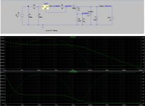
TL431 simulations
Thanks for all your inputs.
After reading much of Thorstens advice I ended up playing around with some basic shunt simulations using the TL431 and LM317/337 CCS.
Attached are some plots for output Z and noise rejection from the source (100mv). Second photo is a comparison of the impact that cap-C4 has on the performance. Results are not great for the Z out compared to salas shunts - but with the tl431 we can get it no more than 2mm away from the pins and probably the smallest current loop possible.
Current through the shunt in this config is set to about 5.5mA (80mW) - which may enable us to use a sot23 or sot89 package and get as close as possible to the pins. Sot89 may be the better option, as you can solder the anode to the pcb as a heat sink but its bigger size will make it a bit more cramped.
It may be a good idea to put only the shunt element itself on V2 (everything after L1), leaving out the other components (ccs, etc). This way people can choose their own recipe. You could even opt not to populate the shunt section at all and have it running the same as V1.
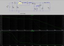
Attachments
Last edited:
Objectively you should build one compare the sound with Salas reg Ryan.
Thanks for all the work that you put in & in sharing with us
cheers
Thanks for all the work that you put in & in sharing with us
cheers
No problem Jaffrie, thanks again for your input.
I think you're right, simulations can only give you at best a ballpark figure. Ill let my ears do the final evaluation. I think the only way to test this circuit will be to place it as close as possible to the pins.
I think you're right, simulations can only give you at best a ballpark figure. Ill let my ears do the final evaluation. I think the only way to test this circuit will be to place it as close as possible to the pins.
Hi Ryan
Hope I'm not a pain to you. To me its not about which is better etc. It's about senergy
to get the best sound. Hell if we all live on specs then non of us will be into this
nos dac bandwagon right. On paper it's not suppose to work at all but in reality it's
totally the opposite
Cheers
Hope I'm not a pain to you. To me its not about which is better etc. It's about senergy
to get the best sound. Hell if we all live on specs then non of us will be into this
nos dac bandwagon right. On paper it's not suppose to work at all but in reality it's
totally the opposite
Cheers
Not at all.
I totally agree, I actually measured the output of the TDA using a 10k sine on a spectrum analyser and was very disappointed with the results - good thing we don't listen to sine waves.
I think there is much more going on with a nos dac than we realise. I'm totally addicted.
I totally agree, I actually measured the output of the TDA using a 10k sine on a spectrum analyser and was very disappointed with the results - good thing we don't listen to sine waves.
I think there is much more going on with a nos dac than we realise. I'm totally addicted.
- Status
- Not open for further replies.
- Home
- Source & Line
- Digital Line Level
- Group buy/Interest list - TDA1541A Core board.