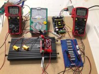
Zoof! A vaporized BJT transistor makes an interesting splatter of carbon on a pricy piece of silicon. But hey, the upside is another recyclable bunch of resources for the junk box.

A fastener that I'd thought had rolled off the bench and onto the floor and gotten lost had instead lodged itself under the HV delay PCB, causing a short to the chassis.
My T-reg TS-5 is setup for 400V and a current limit of 300mA (R16 = 2R7). It regulates just fine.
However, it's current limiting at around 120mA. I measured the voltage across R16 and it's limiting with ~0.3V across R16 rather than at 0.8V.
I wasn't able to get either a BC556B or BC560C for Q5 and used a BC557 available locally. The only significant difference I can see is in hfe. BC557 is only rated as >110. BC556B is 180 and BC560C is 380. Could the BC557 be the problem?
If not, any other suggestions please?
I see that BAT42s are no longer recommended for D7A and D7B and will order some SB140Ts.
Lower Hfe would increase the limiting value, not lower it.
Since you measured the actual limiting value (0.3V) the resistor values are not the cause.
Can you verify the Q2 orientation?
I've seen some with different pinout from different manufacturers but with the same typenumber.
Can you verify, if you short R16, can you get up to 300mA?
Another test is to disconnect R7 from R6 and connect that end of R7 to Vout.
That disables the shutdown.
BTW Do you see just limiting or shutdown?
Jan
Hi Jan. Thanks for the reply.
I see limiting (400V down to around 200V) followed by shutdown after 2 or 3 seconds which is as-designed I think.
Q2, Q3 and Q5 are oriented as per the silk-screening on the PCB. Q2 and Q3 are onsemi BC550Cs so they should be standard pinout. Q5 is a BC557 of unknown brand. My metre reckons it's a standard pinout with an hfe of around 400.
I shorted R16 and the regulator doesn't limit at 200mA which is all my test setup (400V across 22 47k 5W resistors in parallel) can do. I'll add another 14 47k resistors to try it at 300mA and let you know how it goes.
BTW, thanks very much for the regulator. I'm using it to clean up the HT from a cheap (relatively) LLC resonant supply in a 300B stereo amp I'm building.
Dave.
Attachments
Dave, it looks that you supply T-reg from a switching supply.
Any chance that it's that supply that limits Iout?
Have you tested it on itself?
Jan
Any chance that it's that supply that limits Iout?
Have you tested it on itself?
Jan
Thanks Jan. The switching supply is supposed to be good for 300W. I've been using it @ 200mA in the test bed and ~180mA in the 300B amp I'm building for a few weeks without a problem. Definitely the T-Reg that's limiting.
I'll increase the current to 300mA tomorrow.
Dave.
I'll increase the current to 300mA tomorrow.
Dave.

Hi Jan.
I'm very puzzled! My T-Reg doesn't limit on the bench. I don't think it's current limiting is the problem.
I'm investigating lots of possibilities. The problem may well be in the amp itself. It runs OK straight from the SMPS but there's a lot of 100Hz, 200Hz, 300Hz etc noise in the output coming from somewhere. There's a problem there that I'm yet to track down. Maybe there is sudden current spike over 300mA that my metre isn't fast enough to pick up that's causing the current limit to trigger.
Can you answer some questions for me please?
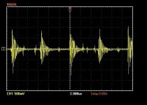
Could MHz region switching noise or residual ~100kHz ripple from the SMPS cause problems for T-Reg? I've attached a screenshot from my oscilloscope.
What would you expect T-Reg to do if the input voltage drops below the set output voltage? One theory I'm investigating is the regulation of the SMPS. Mains here can go from 222VAC up to 247VAC depending on whether the sun is shining; day night but also whether a cloud blocks the sun for a few seconds. Maybe as the mains voltage drops if the SMPS regulation isn't very good, it's output voltage drops as well.
How long would you expect T-Reg to take to settle down to steady output voltage? When I turn it on the output voltage slowly increases by 2 to 3 volts over a few minutes before settling down.
Have you experienced any hysteresis around the trimpot set-point? As I adjust the trimpot approaching my desired voltage of 400V, I get to about 395V and a fraction of a turn later the voltage jumps up to 412V. Then when I wind the trimpot back nothing happens for 2 or 3 turns before it suddenly decreases to 370V-380V. I thought there might be something wrong with the trimpot and took it out and tested it but it was fine. Maybe it's C4 charging and discharging.
When I find out what the problem actually is, I'll let you know.
Thanks and regards, Dave.
I'm very puzzled! My T-Reg doesn't limit on the bench. I don't think it's current limiting is the problem.
I'm investigating lots of possibilities. The problem may well be in the amp itself. It runs OK straight from the SMPS but there's a lot of 100Hz, 200Hz, 300Hz etc noise in the output coming from somewhere. There's a problem there that I'm yet to track down. Maybe there is sudden current spike over 300mA that my metre isn't fast enough to pick up that's causing the current limit to trigger.
Can you answer some questions for me please?
Could MHz region switching noise or residual ~100kHz ripple from the SMPS cause problems for T-Reg? I've attached a screenshot from my oscilloscope.
What would you expect T-Reg to do if the input voltage drops below the set output voltage? One theory I'm investigating is the regulation of the SMPS. Mains here can go from 222VAC up to 247VAC depending on whether the sun is shining; day night but also whether a cloud blocks the sun for a few seconds. Maybe as the mains voltage drops if the SMPS regulation isn't very good, it's output voltage drops as well.
How long would you expect T-Reg to take to settle down to steady output voltage? When I turn it on the output voltage slowly increases by 2 to 3 volts over a few minutes before settling down.
Have you experienced any hysteresis around the trimpot set-point? As I adjust the trimpot approaching my desired voltage of 400V, I get to about 395V and a fraction of a turn later the voltage jumps up to 412V. Then when I wind the trimpot back nothing happens for 2 or 3 turns before it suddenly decreases to 370V-380V. I thought there might be something wrong with the trimpot and took it out and tested it but it was fine. Maybe it's C4 charging and discharging.
When I find out what the problem actually is, I'll let you know.
Thanks and regards, Dave.
Attachments
There's a lot of interacting stuff here. My suggesting would be to attack it one at the time.
Get T-reg working on the bench (linear supply?).
Put an elcap at the input and load the output with a minimum of 5mA to assure regulation.
Maybe just repace the output volt setting resistor and trimpot with a resistor value that sets it to a value 10 or 20V below the output of the bench supply.
Then see if it regulates OK. Increase load and check that the output remains stable up to current limit. Verify that all all loads the bench remains well above Vout, if not then repeat the whole thing with a lower Vout to make sure bench supply is always, any load, well above Vout.
If regulation works, increase load to see if limiting works, do that intermittently, to check the load curent at which Vout will start to drop, that should be the intended current limit.
If that works, increase the time that you put it in limiting and see if it shuts down.
To be safe, do all of that limit stuff at a low current say 50 or 100mA.
The object is not to check max currents but to check the functionality.
Jan
Can anyone explain the purpose/function of D5 (zener diode Z12) in T-regulator circuit? I thought Q1 (FDP12N60NZ) has built in back to back protection zener diodes, therefore making D5 not necessary, right? I read the T_Reg Article document but did not find any info about the this Zener. Thanks.
That was a point of discussion.
Some said that the build-in zener is only rated for high voltage/low current from static from handling and such, but not as protection in a circuit.
I couldn't win that discussion so I added the zener ;-)
Jan
Some said that the build-in zener is only rated for high voltage/low current from static from handling and such, but not as protection in a circuit.
I couldn't win that discussion so I added the zener ;-)
Jan
In principle any power device can be used, but there's a few things to look out for.
You need to make sure that the safe operating area of the device can handle 400mA at the maximum input voltage.
That should be in the data sheet, and is a serious limitation in a lot of high power devices that are meant for switching applications rather than linear.
Some switching device datasheets even don't specify the SOA at all!
The other thing is that the bandwidth and inter-electrode capacitances may make the control loop unstable.
There's no hard and fast way to check that other than just trying it with several loads; possibly a spice sim can shine some light on it too but it's not always 1:1 transposable to a real unit.
So your a bit on your own here.
Jan
Jan,
How do you check for if the control loop is stable/unstable in LTspice with your circuit? Thanks
How do you check for if the control loop is stable/unstable in LTspice with your circuit? Thanks
If it oscillates then the largest signal is usually at the opamp output or at the gate of the pass device.
You probably want to check with light loads as well as larger loads, and with and without extra capacitor at the output.
But also check in real life, not all spice models do accurately model open loop response and capacitances of devices.
Jan
You probably want to check with light loads as well as larger loads, and with and without extra capacitor at the output.
But also check in real life, not all spice models do accurately model open loop response and capacitances of devices.
Jan
Can anyone give me a strategy for debugging one of my regulators please? One doesn't regulate properly. I'm running them side by side at 25V and ~50mA. 45V in.
When I double the load on one the voltage pops up to 29V. I've tried comparing voltages but all I can tell you is that when I halve the load on that one the voltage across R11 increases by 2.5V.
Thanks!
When I double the load on one the voltage pops up to 29V. I've tried comparing voltages but all I can tell you is that when I halve the load on that one the voltage across R11 increases by 2.5V.
Thanks!
What are the opamp input and output voltages when it drops out?
Is D7 the right way around?
Are you aware that R11 is in the neg reg? So that 45V in should probably be -45V in.
Jan
Is D7 the right way around?
Are you aware that R11 is in the neg reg? So that 45V in should probably be -45V in.
Jan
Last edited:
Sorry for the above post, I was looking at the superreg not the T-reg, so forget it.
I'll take a fresh look.
Jan
I'll take a fresh look.
Jan
- Home
- Group Buys
- Group Buy for Jan's high voltage regulator