the Ground Loop Breaker (Disconnecting Network, DN) is between the audio ground and the chassis. Surely at this testing phase you have no chassis and thus no connection that can benefit from a Disconnecting Network
I am testing with test chassis which has all the elements like 3-pin power inlet, fuse, toroid, heat sink, chassis ground, etc. its not pretty but works.
I tested with pre-amp removed and only amp (having HBRR and HBRL) with volume pot, there is only slight hum which is volume independent that can be heard only if I place my ears to speaker.
When I had tested with pre-amp there was the hum that was volume dependent (I thought hum due to gnd loop was volume independent) , which makes me wonder if the hum when pre-amp is introduced is really gnd loop hum!!!
regards
prasi
hum! what does it measure?
This probably indicates you have a wiring error.
But because it is in a chassis I can't tell whether it is an earthing fault, or a ground loop fault, or an audio fault.
This probably indicates you have a wiring error.
But because it is in a chassis I can't tell whether it is an earthing fault, or a ground loop fault, or an audio fault.
To follow D. Joffe method you will also need two separate input Grounds for the pre-amp (GNDA-L and GNDA-R), this looks impossible with the current layout.
Still unclear about the PSU configuration. I see that the pre is supplied by +/-12. What is supplying the power amp?
Still unclear about the PSU configuration. I see that the pre is supplied by +/-12. What is supplying the power amp?
To follow D. Joffe method you will also need two separate input Grounds for the pre-amp (GNDA-L and GNDA-R), this looks impossible with the current layout.
Still unclear about the PSU configuration. I see that the pre is supplied by +/-12. What is supplying the power amp?
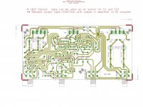
although the audio grounds are separate they are meeting at the same common point (star audio ground) in layout. here is the layout including HBRR and HBRL.
Regarding the PSU, the same PSU is supplying both the amp and pre-amp (+/-12V for pre-amp and +/-32 V for amp.). It is a very simple PSU with caps and regulators (for pre). Since it is a bought out item I dont have the schematic nor layout. It has a common ground trace for both 12V and 32V.
Attachments
HBRR and HBRL are inparallel and equivalent to adding a single resistor of half the value. Its a dilemma.
It has a common ground trace for both 12V and 32V.
I'm not sure that the ground lift resistors are correctly placed. And I don't know why there are two, essentially in parallel. And I get even more confused when I see the resistors are actually bypassed by the ground return of the film caps used for decoupling the opamp supplies.
The audio ground and power ground of the preamp are to be separated. Applies to both input and output ground. Also a very good practice in power amps.
The input tracks must be close to each other upto the wiper of the potentiometer. The pot can then be wired directly to the signal ground.
The way I like to do this for silent speakers is have two sets of ground for power and preamps. Signal ground and power ground. Since you already have a ground common inside the power supply PCB, this job becomes quite difficult. It would be best if you could locate the ground common and physically separate them.
Even if you persist in this direction, the least you could do is to use the power supply ground wire to the preamp as a return only for the decoupling caps. Everything else would connect to the signal ground, and this point could be returned to the power supply ground with a single track on which you can install a ground lift resistor.
The way you need to visualise this is to see how the currents flow. The input current flows through the pot from terminal 1 to 3. The pot output current flows from terminal 2 to 3. And so on. Long, thin, inductive tracks never help your cause.
The layout looks painfully complex. Try rotating the opamps by 90 degrees so you don't have to use such roundabout tracks. And don't flow opamp power through the decoupling cap track. Route power to the supply pin, then tap it out for decoupling.
Follow the currents.
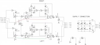
Mark's sch in post47 shows the best and clearest way to draw the input circuit.
One can SEE the circuit around which the source currents must Flow and Return to the Source.
Using that sch: attach the output to a Power amp that has the input Return commoned somewhere inside the casing.
Attach the input of this pre-amp to a Source that has a commoned Return.
Now you have a loop that includes the two returns through the preamp.
This loop has wires that carry signal. Any interference that gets in the loop will mix with the signal.
That is what HBRR and HBRL are there for. They attenuate the interference current without attenuating the signal current. HBRR and HBRL need to be located in the Loop but OUTSIDE the signal circuit.
Look at D.Joffe's fig5 and see why his location is IN THE LOOP but also OUTSIDE the signal circuit.
Guys,
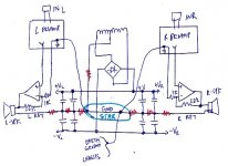
I have been busy on other things. I started thinking about the grounding again. It is more complicated, you have two separate power amps, particularly if one want to do better and use separate banks of capacitors for L and R side. It is much harder to do that. I think this is very relevant for this discussion.
Attached is what I came up so far, this is by no means the answer, this is more like a draft I came up with and I want to get opinions also as I am building the amp with 40mF for each rail for each side. The total capacitance is 160mF. I drew up the sketch of how I envision the two banks of caps and ground are separated. I drew the wire resistance in RED to show where the longer wire is.
I basically try to separate the two sides all together.
I use an opamp as the symbol of the power amp. I use the ground of the preamp as the reference to the input of the power amp to avoid ground loop. This should make the noise on the power amp ground( labeled L RET and R RET) as common mode noise to the preamp. I hook the speaker returns to this same power amp ground.
The single point ground is shown in light blue, the preamp ground is referenced to this one point ground, so is the earth and chassis ground.
Please comment on this.
Thanks
Attachments
Last edited:
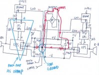
I since modified more. This time, I even separated the ground return of the IPS/VAS and the preamp from the noisy ground of the two OPS.
The OPS really does not need ground except for the smaller rail filters on the OPS board. The ground reference of the power amp(opamp consists of IPS/VAS and OPS) is referenced from the ground of the preamp as before which got the ground at the "Star" ground shown.
IPS/VAS only connected to the OPS by two wires that connect to the top and bottom of the bias spreader. So the both the L-RET and R-RET is isolated from the Star ground by a few inches of 12 Gauge wires.
With this, I intentionally put a little length from the Star grounding point to the two reservoir caps on each side. The Star is connected to the earth ground and chassis as the quiet ground where the IPS/VAS and the preamp reference to.
Both the IPS/VAS and the preamp should have 22ohm resistor in series with the +V and -V before the internal filter caps on their own pcb to filter out the noise on the +V and -V.
If people are really anal about this, I can envision you have filter caps for the IPS/VAS and the preamp that reference to the Star ground to become the third bank of filter capacitors. Now you have one bank for each OPS, then a third bank for the IPS/OPS and preamp.
Attachments

Last edited:
You have shown a centre tapped transformer.Guys,
I have been busy on other things. I started thinking about the grounding again. It is more complicated, you have two separate power amps, particularly if one want to do better and use separate banks of capacitors for L and R side. It is much harder to do that. I think this is very relevant for this discussion.
Attached is what I came up so far, this is by no means the answer, this is more like a draft I came up with and I want to get opinions also as I am building the amp with 40mF for each rail for each side. The total capacitance is 160mF. I drew up the sketch of how I envision the two banks of caps and ground are separated. I drew the wire resistance in RED to show where the longer wire is.
I basically try to separate the two sides all together.
That means you MUST connect the Main Audio Grounds together. You cannot "try to separate the two sides all together."
The two sides MUST share the common PSU Zero Volts.
I use an opamp as the symbol of the power amp. I use the ground of the preamp as the reference to the input of the power amp to avoid ground loop. This should make the noise on the power amp ground( labeled L RET and R RET) as common mode noise to the preamp. I hook the speaker returns to this same power amp ground.
The single point ground is shown in light blue, the preamp ground is referenced to this one point ground, so is the earth and chassis ground.
Please comment on this.
Thanks
you have separated the smoothing cap junction from the centre tap with a resistance. This will create a BIG charging voltage across the resistance.I since modified more. This time, I even separated the ground return of the IPS/VAS and the preamp from the noisy ground of the two OPS.
The OPS really does not need ground except for the smaller rail filters on the OPS board. The ground reference of the power amp(opamp consists of IPS/VAS and OPS) is referenced from the ground of the preamp as before which got the ground at the "Star" ground shown.
IPS/VAS only connected to the OPS by two wires that connect to the top and bottom of the bias spreader. So the both the L-RET and R-RET is isolated from the Star ground by a few inches of 12 Gauge wires.
With this, I intentionally put a little length from the Star grounding point to the two reservoir caps on each side. The Star is connected to the earth ground and chassis as the quiet ground where the IPS/VAS and the preamp reference to.
Both the IPS/VAS and the preamp should have 22ohm resistor in series with the +V and -V before the internal filter caps on their own pcb to filter out the noise on the +V and -V.
If people are really anal about this, I can envision you have filter caps for the IPS/VAS and the preamp that reference to the Star ground to become the third bank of filter capacitors. Now you have one bank for each OPS, then a third bank for the IPS/OPS and preamp.
You then connect all your Audio references and returns to this modulated "point". This will ADD noise to your audio channels.
Start again.
you have separated the smoothing cap junction from the centre tap with a resistance. This will create a BIG charging voltage across the resistance.
You then connect all your Audio references and returns to this modulated "point". This will ADD noise to your audio channels.
Start again.
I don't follow you. The Star ground is reference to the earth ground and make it 0V. The charging current will create voltage across the wire resistors between L_RET/R_RET and the Star. But the noise will be on L-RET and R_RET, not on the Star. This is because the Star is truly a one point ground referenced to the earth ground.
Also, there will be big ripple voltage across the wire resistor between the CT of the transformer and the Star. BUT again, the whole secondary of the transformer is floating. The whole transformer might be bouncing up and down due to the ripple current, but that does not affect the Star.
Note that the preamp driving the power amp differentially, the two ground is not the same. The ground of the 1K resistor is grounded in the preamp ground, nothing to do with the R_RET of the OPS. The IPS/VAS only have the + and - signal, again no ground.
Go through it again, this is a true one point ground. The output is referenced to the preamp and IPS/VAS ground directly from the star.
Last edited:
The circuit in post 50 appears to have been designed to maximise the buzz. I assume this was not the intention? You need to do some more thinking about whwre the currents flow, and what voltage drops they will produce. Bear in mind that unless you have fully balanced interconnects throughout the system you cannot separate left and right ground and expect them to stay separate. A major cause of hum is people expecting two points to be both separate and connected, at the same time.
Schematic with ground disconnect at the inputs. Needs some work on the balance potentiometer GND connection.
Hi Mark and Andrew,
Something like the attached sch is what I should aim for? In thats the case, then really whether I need HBRR and HBRL on pre-amp also? Or they should be only located on power amp ? Keep and power and signal grounds seperate and join them together only on amplifier with HBRR and HBRL
regards
prasi
PS. I have added a dual gang pot for left and right balance control.
Attachments

Last edited:
I drew out one of the current path starting from the right leg of the transformer
1) through the rectifier to +V.
2) Through the 40mF filter cap on the right channel
3) through the 40mF filter cap.
4) through R3 to the Star ground.
5) then through R1 back to the CT of the transformer back to the starting point shown.
The Stat is GROUNDED to 0V to the earth ground and there is no other reference point in the whole system. There is NO CURRENT from the Star to the earth ground. So this point is quiet.
I labelled the wire resistors R1, R2 and R3, I also label the polarity across the wire resistors according to the current loop as if it's DC current. You can see all the + side of the resistors are "grounded" to 0V, so the other side of the resistors all have -ve voltages. This indicates all the ripple voltages are on the transformer, L-RET and R-RET.
Since the IPS/VAS and the preamp are all referenced to 0V earth ground, there is no noise. Granted you are going to have ripple on the +V and -V that power up the IPS/VAS and preamps, I did specify you need a 22ohm in series before going to the first filter cap on the pcb of IPS/VAS and preamp. The noise is all dropping across the 22ohm. This will be small current as it's limited by the 22ohm already. It should not bounce the GND and the Star.
You can draw out the current path for the left side, the result is exactly the same. You just have two loops connected at only ONE POINT at the Star. It will not change what I described above.
Be aware that the preamp is driving the power opamp DIFFERENTIALLY with the 1K resistor reference to the preamp GND. So the input of the integrated amp is referenced to GND. GND is not affected by the ripple on L-RET, R-RET and the transformer.
Attachments
Last edited:
Hi Mark and Andrew,
Something like the attached sch is what I should aim for? In thats the case, then really whether I need HBRR and HBRL on pre-amp also? Or they should be only located on power amp ? Keep and power and signal grounds seperate and join them together only on amplifier with HBRR and HBRL
regards
prasi
PS. I have added a dual gang pot for left and right balance control.
R6 - R10 - Load Returns should connect to the PGND.
The goal here is to separate the grounds at the inputs and have a single output/power ground for each peace of equipment.
This voltage is applied to the speaker 'ground' connection so will introduce buzz. The NFB can't reduce it because the NFB is simply controlling the voltage applied to the other speaker terminal - it doesn't know the total voltage across the speaker yet it is this which determines what you will hear.Alan0354 said:through R3 to the Star ground
However you do it, putting the star point in the middle of the charging loop is a bad idea - yet extremely popular.
This voltage is applied to the speaker 'ground' connection so will introduce buzz. The NFB can't reduce it because the NFB is simply controlling the voltage applied to the other speaker terminal - it doesn't know the total voltage across the speaker yet it is this which determines what you will hear.
However you do it, putting the star point in the middle of the charging loop is a bad idea - yet extremely popular.
The whole grounding is a true one point ground at the Star, you will not find any ground connection between preamp to IPS input, you will not find ground connection from IPS/VAS to the OPS. This is a clean grounding scheme.
The speaker ground is L-RET and R-RET. It is designed to bounce with the hum as the charging current is high. BUT if you look at the Star, that is connected to earth ground and is quiet. The preamp and IPS/VAS are referenced to the Star.
If you look at it in detail, there is NO ground connection between the IPS/VAS to the noisy OPS. The two signals + and - are from the VAS to the bias spreader of the OPS, there is no ground reference. This is very important. This way, the whole circuit is reference to the Star ground from the preamp, nothing to do with the speaker return. The noise on the L-RET and R-RET become common mode voltage and will not affect the signal.
Also, if you look at the interface from the preamp to the IPS, it is differential connection. The ground reference of the 1K gain resistor is from the preamp.
These are very important points that AndrewT missed. This a a complete design to separate the noisy ground from the Star that the preamp and IPS/VAS used. Then using differential signaling to make the noise common mode.
Last edited:
Explain to me how a feedback loop fed from one side of the speaker (referenced to a particular ground point) can correct for a buzz signal injected to the other side of the speaker. A feedback loop can only correct what it sees; if you hide something from it then it won't correct it.
This is a design to inject noise currents through the star and yet expect the amp to remain buzzless!! It is the usual dirty grounding of a newbie.
This is a design to inject noise currents through the star and yet expect the amp to remain buzzless!! It is the usual dirty grounding of a newbie.
- Status
- Not open for further replies.
- Home
- Amplifiers
- Solid State
- grounding issues with integrated amp