To be honest, I've never understood this statement on the Sziklai's.
I verified this in sims, and it works out. Self details this as well in his excellent book.
And this is a nice feature, instead of using regular darlingtons, it's much better to use sziklai instead, as they're better performers that way and much easier to thermally control. Plus when using sziklai, fewer junctions are "visible" to the bias spreader. When doing a 2EF, that's 4 junctions seen by the spreader, and 3EF makes that 6. Quite a bit. While using sziklai instead of darlington as a 2EF, it's just 2 junctions instead of 4.
And the best part is that only the drivers need to be thermally coupled with the bias spreader sensor device, whatever it may be. And the rest of the devices, the outputs, can be on their own sink, not tracked, as they don't influence the bias current much. No risk of runaway.
The drivers don't dissipate very much compared to the outputs, so small sinks are quite sufficient, and the thermal coupling with the bias spreader sensor can be made much more "intimate", with a much better thermal resistance situation, and since those sinks are so small and the coupling tighter, the thermal lag to make correction is much better.
So although a lot of diyers swear by those 2EF and 3EF, since they're a little more difficult to stabilize and less linear, I don't see why not make good use of the sziklai topo?
Do they possibly use forced convection by a fan?
They do, although not in all amps, make use of forced convection, but it's not on all the time, and it's very grossly done, in my opinion. I just take that as a simplified attempt at thermal regulation, but it can be skipped altogether, since they have a PTC on the main sink that causes a shutdown if it gets too hot.
According to one of their builds that I looked at, the fan only comes on when the main sink reaches 60C, which only happens some of the time, unless the amp is pushed pretty hard.
Those amps are reputed for their robustness. And their topology allows for many interesting savings, making amps more compact, lighter, and cheaper to make, with a lower part count.
QSC has been doing this for a long time and even their latest amps, except for the class D, still use the grounded collector topo.
What I found interesting as well, is that to make more powerful amps, they make use of class G and H topos, and all while retaining the grounded collector as well.
I'm not too fond of the class G and H, as it's virtually impossible to get rid completely of the switching artifacts between rails, and this added to the crossover issues, it's tricky to make amps with low distortion.
Fact is, when you look at the specs on all those amps, there aren't any stellar thd performance announced, they tend to be at something like less than 0.1%, and sometimes it's even 1%.
The grounded collector topo makes the big filter caps also be the output coupling, which does increase somewhat the distortion, as the signal must pass through them, however, at the same time, this topo prevents any possibility for DC to make it to the speakers.
The only way for DC to ever reach the speakers is in the case of a filter cap failure that shorts it, which is fairly rare.
QSC does add DC detection, not to all amps though, and their action in case of DC detection, is to throw a crowbar across the output.
Surely that's a kind of speaker protection against the speakers, but depending on the type of failure in the amp, if a filter cap is shorted, and the crowbar is thrown, then I suspect much more damage gets to spread, starting with the outputs.
But one can't deny the many advantages of this grounded collector topo. I can understand why they stick to it. It's economically sound, makes for lighter and more compact amps, simpler, cheaper... And this can obviously be made robust, as they're doing it.
For outdoors PA, I think it's a sound choice.
Our current design is coming together and we actually are getting, at least in sims, some rather nice performances. Our current version has rather low thd, that might be difficult to reduce much further, but this is good as is, and far better than anything announced in the specs of any such amps out there.
A little more tweaking is needed to attempt to minimize the spikes of thd at some frequencies, but this should be feasible.
I'm looking closely at the thermal situation, but this seems to be fairly easy and not so much of a concern, by comparing with what QSC does.
I'm trying some configuration of the bias spreader to increase the thermal control, but this is icing on the cake.
For my latest sims, assuming all devices are on the same main sink, plus that extra diode added lately, which remains at ambient, the rise of bias current in the outputs represents only about 35-40mA with a 50C temp rise on the sink.
This doesn't seem to me like a thermal runaway candidate.
I was looking at the QSC MX700 design, and as far as I can see, they have the fan running at 2 speeds, always on, but low speed most of the time, and a temp sensor kicks it to full speed over 60C.
It's super simple, no electronics to trigger that, just a thermal switch that activates at 60C.
They do have other thermal protection, independent of that, with PTCs, for a thermal shutdown, which I suspect would never activate unless the main fan either broke down or became insufficient for some reason.
I don't think throwing a crowbar for thermal reason is a good thing, and I'd rather do some kind of partial muting, or better yet, compression/limiter.
In case of clipping, there is less risk of DC forming and going to the speakers, but preventing clipping with a limiter would be a nice feature.
The limiter at the amp's input could be driven by a clipping detector, and could also be activated by a thermal detection system.
I did some simulation of a limiter and the only part of it I can't work out, yet, is the actual limiter itself, not the detection.
Having looked at the many methods to limit the input, I am in favor of using the vactrol, which is used in many amps and even by mcintosh and with the type of detection made with an opamp, this is a very transparent method, rather simple and efficient, with few side effects, of done right.
The only thing hard to work out is that vactrol part.
So, why not use a double Sziklai (NPN-PNP-NPN and PNP-NPN-PNP) instead of a 3EF config?I verified this in sims, and it works out. Self details this as well in his excellent book.
And this is a nice feature, instead of using regular darlingtons, it's much better to use sziklai instead, as they're better performers that way and much easier to thermally control. Plus when using sziklai, fewer junctions are "visible" to the bias spreader. When doing a 2EF, that's 4 junctions seen by the spreader, and 3EF makes that 6. Quite a bit. While using sziklai instead of darlington as a 2EF, it's just 2 junctions instead of 4.
And the best part is that only the drivers need to be thermally coupled with the bias spreader sensor device, whatever it may be. And the rest of the devices, the outputs, can be on their own sink, not tracked, as they don't influence the bias current much. No risk of runaway.
...
So although a lot of diyers swear by those 2EF and 3EF, since they're a little more difficult to stabilize and less linear, I don't see why not make good use of the sziklai topo
While running a PA System, you don't really want an amplifier shutdown in the middle of a show, do you?They do, although not in all amps, make use of forced convection, but it's not on all the time, and it's very grossly done, in my opinion. I just take that as a simplified attempt at thermal regulation, but it can be skipped altogether, since they have a PTC on the main sink that causes a shutdown if it gets too hot.
Although I'm not really able to contribute usefully, this thread is very interesting and fascinating to me. I'll keep following!
Best regards!
So, why not use a double Sziklai (NPN-PNP-NPN and PNP-NPN-PNP) instead of a 3EF config?
Yes, definitely, that's my point exactly.
So many are stuck on that 3EF, which has some issues to master, while the sziklai has fewer issues and so many advantages in comparison.
I would definitely favor that topo.
Actually our current grounded collector design isn't even that complex, and it's not 2EF. I was thinking it was more akin to the sziklai topo, but the sims confirm it's not quite the same, although it seems to be somewhat thermally stable, and not too difficult to get working right.
While running a PA System, you don't really want an amplifier shutdown in the middle of a show, do you?
Exactly! I don't like the crowbar method at all, for that reason, while there are so many other far less intrusive things to do, to keep it safe and running with no show stopper.
I really like the limiter idea, which can be triggered by more methods than simply a clipping detection.
A limiter can be triggered by a thermal protection, the muting system for powerups and shutdowns...
A limiter based on a vactrol should be very transparent, not introducing extra distortion, at least not when inactive, and even when activated, it should hardly be disturbing, just limiting drive level.
I've been looking into this for quite some time, and compared a lot of methods, and so far, my favorite is the vactrol at the input. Some of QSC's models are actually using that method, such as the EX800 for example. They use their own detection method, but then applying the compression is done by the vactrol.
It's too bad the vactrols are a bit on the slow side, but it's not too bad, and they have mostly advantages otherwise.
One thing is definitely an advantage with the grounded collector, the cooling is easier, simpler, cheaper, with much smaller heatsinks.
If this is combined with SMPS instead of ordinary transformer based PSUs, like it is in QSC's powerlight models, then it's not only very compact, it's also quite light, and more efficient. Very good plusses for touring, with much smaller and light amps.
I'm a bit wary of SMPS, because of the high frequency stuff mostly, and possibly the lower reserve for transients, but if over-designed for extra headroom, perhaps it can be a good thing in such amps.
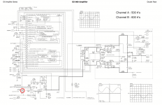
Here is one example from QSC, for the use of a vactrol at the input for drive level limiting.
They trigger it from more than just the signal, as the thermal info is also used.
Although they don't show much detail about what's going on in those boxes in the dotted area.
This is an "ordinary" grounded collector amp.
One thing I don't like about it is using an electromechanical relay at the output.
The PSU couldn't be any simpler.
Attachments
I've been running a big range of comparative sims to find an optimal bias for lowest thd.
Since it can't be quite the same at all frequencies, although some ranges are in common, it's not throughout the audio spectrum, but somewhat close, and as it stands right now, the way our current version is, this optimal bias range seems to be roughly in the 146-148mA, for each output device (4 pairs).
This is a little rich and generates some heat.
As I've been looking at many topos, some similar, some less, and read that one possible and somewhat commonly used method is to bias as Class AB+B, with hardly any current, if any, in the output devices, while the bias is comfortably set for the drivers, and pre-drivers (if any), to avoid the crossover as much as possible and work as class A a little bit, then the outputs come into play on larger signals.
Perhaps we can explore this a little.
Right now we have a little less than 70mA of bias in the drivers, and I saw that this wasn't changing much with temperature, when everything is thermally coupled on a common sink.
Maybe having a lot of bias in the outputs isn't so necessary.
I did more simulation on the vbe multiplier, seeking a stronger thermal correction. Adding diodes in this vbe multiplier in various ways, and I haven't found one that would completely control the rise in bias current in the output, however, to keep that current under control in the outputs, the bias current in the drivers must drop to counteract the rising current in the output, and eventually there could be too little left in the drivers.
As the attached plot shows, to better level off the output's current with the temp rise, it would require lowering more the current in the drivers.
So it's a compromise, and it looks like such a compromise isn't really that bad, with a bias current rise in the 30-40mA range in the outputs with a temp rise of some 50C, which would be about the max we would allow anyway, as an other temp protection should monitor the sink temp and do something to curb any further rise, such as kicking in a fan, limiting input drive level, or in the extreme, thermal shutdown if need be.
Adding diodes in the vbe multiplier does add a tighter control, and the strongest is by thermally coupling them with the main sink of course, instead of leaving them at ambient temp. But thermally coupling diodes with a sink, when they're in some DO type case, isn't so easy and efficient, however, having looked at how QSC does it, this doesn't seem that important, and there would be some thermal lag, but no runaway.
When really hot, the bias current in the output would rise some, while the drivers would see a little drop.
The comparative sims that I ran to find the sweet spot of optimal bias at various frequencies showed a compromise need to be found, and when factoring in those temperature related changes in bias, I suppose the best way is to pick a lower than optimal bias at room temperature, that would make it more optimal when warm. And that warm temp would be an average possible level that would be encountered most of the time in normal usage.
When the temp would rise some more when under heavy usage, then the bias would rise above optimal, without a runaway, eventually the forced cooling could kick in, keeping it under control, and in case of extreme abuse, then some additional measure could prevent going too far.
I have tried one other thing, because I was curious about that topo, which was to make the vas cascode a hawksford type, and although it is better and improves thd, it's not a big difference, so not really a big deal.
And lastly, since we still have that "bump" of thd at the low end, with a serious thd rise to well over 0.1%, compared to our rough average mostly in the 20-30ppm in the remaining spectrum above 200hz, I took a look at what could be causing this.
I just can't see anything else besides the caps that could cause such a thd rise at the low end.
I tried higher cap values for the feedback and input coupling, which works quite well, but I haven't yet run a full spectrum thd analysis to find out exactly how it affects things.
That's my next goal. I will try higher cap values and compare their effect on thd over the whole spectrum.
The big filter/coupling caps were also investigated earlier and I had found a sweet spot could be found to lower thd at the low end as well.
I'm really curious to know how those big filter cap values are determined by calculation. What comes into play, and why we do have a sweet spot.
Attachments
- Status
- Not open for further replies.
- Home
- Amplifiers
- Solid State
- grounded collector amp