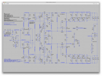
I'm curious if adding a resistor divider at the VAS base will bring that drive down. I tried 22k, just a swag.
I didn't see that at first. But this is more like an additional load for the ltp isn't it?
Wouldn't that tend to make it sag some more because of higher load?
I'm curious if adding a resistor divider at the VAS base will bring that drive down. I tried 22k, just a swag.
That brings the vas bases barely 2v away from the rails, which I assume is more or less what you're trying to achieve.
At the same time, obviously this reduces drastically the vas bias current, and as you can see it takes the bias spreader trimmer to its limits. Yet still adjustable and the offset adjustment also still works, close to their limits.
I'll change the vas load res to bring back a more "normal" bias...
Attachments
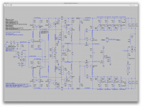
Here it is. Bringing the vas load res down to 56ohms gets us about 22mA vas bias.
We get an operating point with less extreme adjustment for the bias spreader and the offset.
Please note that I also had previously brought down to 150k those res on the miller comp at the vas, and the extra caps on the drivers were down to 47p.
That was necessary to get rid of some tiny oscillation remnant that was still discernible on the sine wave, and I could no longer see if after that. The thd also got better as well.
But not the phase margin though.
Attachments
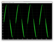
Getting rid of oscillations... (not quite 100% yet)
This time the caps on the drivers do need to get bigger.
And the res on the miller caps at the vas need to drop down from 180k as well.
We can still discern signs of left over oscillations, and yet, thd is looking better.
This time the caps on the drivers do need to get bigger.
And the res on the miller caps at the vas need to drop down from 180k as well.
We can still discern signs of left over oscillations, and yet, thd is looking better.
Attachments

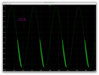

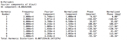
I figured it wouldn't cost anything to try increasing a bit the cap values on the drivers, and sure enough, at 120p we no longer can see oscillation artifacts on the sine wave.
And we have improved things on the ac analysis, by pushing further down and at higher frequencies the spike of gain that was at 2mhz before, and it's smaller in amplitude as well.
If we could drag that spike down below unity gain and further up in frequency, we should be able to obtain some good phase margin.
I tried 150p, but things got worse instead of better, so here as well we do have a bit of a sweet spot somewhere.
Attachments
Going on a hunt for some phase margin, and taming that gain spike near 2mhz.
Having brought down that spike a little with those driver caps at 120p and the res at 150k on the vas miller caps, I figured I'd try pushing that spike down further, and managed to do so by increasing a bit the global feedback comp cap to 6p8.
This was bringing back oscillations before, but so did values over 47p on the driver caps, so why not?
At 6p8, the gain spike does drop below unity gain and moves up to about 4mhz, instead of 2.
This does change things a bit, with a beginning of a phase margin, insufficient for now, but a tiny bit over 25 degrees.
I'll see what happens now to the ac analysis...
Attachments


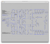
If it were me, I will start with a single output pair, single driver, simple VAS and no ccs in LTPs. But then I am a complete novice in simulating anything !
I'm looking at the oscillation. It seems to be around 4mhz. I need to understand where it originates, and I suspect in the output stage. An output stage with gain is unconventional, because it is very difficult to stabilize driving complex reactive loads. Here we are stuck with it, since our 15v front end must scale up to 60v.
If my hunch is correct, change the output stage. So, I attach a variation. I am trying to break free of the oscillation problem with a different scheme. The front end is unchanged. The output stage is back to a triple. I am using a very stable double emitter follower for current gain only. Voltage gain is about 6 at the MJE3xx predrivers. Compensation is approximate, and should be experimented with freely. I am not sure this is an improvement, only the simulation will tell.
If my hunch is correct, change the output stage. So, I attach a variation. I am trying to break free of the oscillation problem with a different scheme. The front end is unchanged. The output stage is back to a triple. I am using a very stable double emitter follower for current gain only. Voltage gain is about 6 at the MJE3xx predrivers. Compensation is approximate, and should be experimented with freely. I am not sure this is an improvement, only the simulation will tell.
Attachments
In my previous schematic, the predriver is only supplying 4ma to the output double, probably too low. Increase it as needed by decreasing the 22k and 3.3k resistors on the predriver emitter, keeping the ratio about 6 for gain of 6. I was trying to keep dissipation in the resistors down, but we need the current, so they will be high wattage, that's OK. The gain of 6 is not sacred, just the lowest that works. Maybe gain of 10 would be OK and allow higher currents, if we used say 10k and 1k.
Last edited:
If my hunch is correct, change the output stage. So, I attach a variation. I am trying to break free of the oscillation problem with a different scheme. The front end is unchanged. The output stage is back to a triple.
The local feedback at the output is what I suggested, about 100 answers before. Using EF driver takes You closer to the Crest Audio PROX200 output stage.
Sajti
Saitj said: The local feedback at the output is what I suggested, about 100 answers before. Using EF driver takes You closer to the Crest Audio PROX200 output stage.
I say: Thanks for your suggestion, we welcome all.
If you look at the Bode plot it has a pathological behavior, with gain kicking up at 2Mhz to above 0db. I've never seen such a nasty gain curve. It makes the amp unstable. The cause of the gain peak is not obvious. But my strongest hunch is the CFP in the output is the villain. My latest change discards the CFP in the output, because I suspect it might be the source of a 4 MHz oscillation showing up in simulation.
The alternative to CFP, a double EF, still has lots of current gain, but voltage gain less than one so it is less likely to oscillate. There is only voltage gain in the output stage at one predriver, a very simple thing to analyze, and apply compensation to in well understood ways. That's the plan, at least.
I frankly don't know if this is going to work better. It's based on the assumption that the CFP is the source of the problem. If that is wrong we step back and rethink the problem.
I'm looking at the oscillation. It seems to be around 4mhz.
That is the case in our latest incarnation and with the types of compensation and adjustments that I made. Otherwise that oscillation was happening at a lower frequency before, which seems to me to be the same at the top of the gain spike that we see.
What is puzzling is that once that gain spike has been pushed down below unity gain and at higher frequency, and as a result the phase shift happens higher to allow for some phase margin, the oscillations still want to occur.
I need to understand where it originates, and I suspect in the output stage. An output stage with gain is unconventional, because it is very difficult to stabilize driving complex reactive loads.
Bryston uses gain in their output stages all the time, and we know how good their amps are.
I am using a very stable double emitter follower for current gain only. Voltage gain is about 6 at the MJE3xx predrivers.
This definitely reminds me a bit of Bryston's stages.
Compensation is approximate, and should be experimented with freely. I am not sure this is an improvement, only the simulation will tell.
Looks promising.
In my previous schematic, the predriver is only supplying 4ma to the output double, probably too low. Increase it as needed by decreasing the 22k and 3.3k resistors on the predriver emitter, keeping the ratio about 6 for gain of 6.
Actually it has a different influence on the vas stage as well, and the bias current went down quite a bit in the vas, so I chnaged their load res back to 47ohms, so we end up with a little more than 21mA now, which helps the bias spreader function and turns on the pre-drivers. Otherwise we get dead silence there.
I was trying to keep dissipation in the resistors down, but we need the current, so they will be high wattage, that's OK.
Once it's functional, I can add data labels with the power dissipation in those res, so we'll have a better idea then.
The gain of 6 is not sacred, just the lowest that works. Maybe gain of 10 would be OK and allow higher currents, if we used say 10k and 1k.
I tried raising those in stages, until the O.Ds finally turned on.
I ended up with raising the drivers' emitter res to 18ohms, or the O.Ds wouldn't turn on.
Ended up with 1k2 and 12k on the pre-drivers emitters. Gain of 10. And this works, giving us an operating point.
I must point out that without the input offset correction, the rails don't center.
Every time we start with a radically different scheme as it's the case now, I disable that offset corrector to see if it'll work without it, but it doesn't and it always takes both the bias adjustment and offset correction to bring it to a good operating point with the rails centered. As I mentioned earlier, and it's still the case here, the range in which each adjustment works in the trimmers is rather narrow, so a small change causes serious repercussion. The offset adjustment is even more abrupt than the bias one.
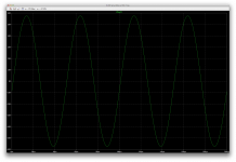
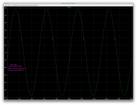
Anyway, once I had a good operating point, I let it rip with a 20khz sine and we get a lot of oscillations, although this looks like a radically different behavior than before, and those oscillations at first glance seem to be of much lower frequency.
But I arbitrarily set the miller caps at 47p, with the res on those caps at 180k and the comp caps on the pre-drivers untouched at 100p, with no attempt yet at adjustments. The global feedback comp cap also unchanged from previous attempts at 6p8, so this doesn't mean we won't stop the oscillations.
We do have the output coil and its res to tweak as well, eventually.
I think there is also a possibility of comp caps on the pre-drivers emitters, as in the bryston amps...
Attachments


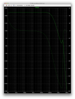
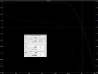
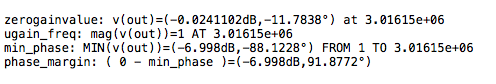
Without much adjustment yet, the miller caps still at 47p (& 180k), the global feedback comp cap at 22p and the comp caps on the pre-drivers unchanged at 100p, we have a much nicer looking frequency plot with a nice roll off and no gain spike at all. The phase shift reversal does happen but far less important and this should be much more easily tamed.
We have a good shot at taming this beast.
We already have a phase margin in the order of 38 degrees as it stands now.
We have a good shot at taming this beast.
We already have a phase margin in the order of 38 degrees as it stands now.
Attachments
I would add the collector resistors, for Q28, and 29. Using just the basecurrent of the drivers, makes the parameters very undefined.
Sajti
Sajti
I would add the collector resistors, for Q28, and 29. Using just the basecurrent of the drivers, makes the parameters very undefined.
I think you're quite right. I was wondering about this while drawing it up...
I tried 47k but settled on 100k for now, until we get this to a better suited value.
Anyway, just to see what's going on a bit better, I ran a few "what if" sims. Because although we have serious oscillations, I can feel we have good potential for taming that.
And I was wondering what role those caps would have on the pre-drivers.
So here are a bunch of shots with various values and locations for caps on pre-drivers.
I kept the miller at 22p and the global feedback comp cap at 4p7 for all these tests, for good comparison.
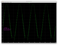
We can see that caps on the pre-drivers' C-B don't do much, if anything, to stop the oscillations, however when moved to the emitter res, it changes everything.
Having caps on both of the pre-drivers' C-B and their emitter res doesn't stop oscillations, so I suppose they should not be used there on the C-B but rather on the emitter res only.
The values used reveal a sweet spot and overly high values are to be avoided.
I also tried with 470p and it got even worse than with 330p. (not enough room here to post that screen shot)
Attachments
-
 Screen Shot 2016-11-29 at 12.07.42 PM.png264.3 KB · Views: 53
 -
 Screen Shot 2016-11-29 at 12.07.19 PM.png261.4 KB · Views: 50
 -
 Screen Shot 2016-11-29 at 12.06.54 PM.png261.3 KB · Views: 71
 -
 Screen Shot 2016-11-29 at 12.06.27 PM.png260.8 KB · Views: 60
 -
 Screen Shot 2016-11-29 at 12.06.02 PM.png261.1 KB · Views: 53
 -
 Screen Shot 2016-11-29 at 12.05.33 PM.png317.4 KB · Views: 53
 -
 Screen Shot 2016-11-29 at 12.04.53 PM.png263.9 KB · Views: 56
 -
 Screen Shot 2016-11-29 at 12.02.38 PM.png325.3 KB · Views: 56
 -
 Screen Shot 2016-11-29 at 12.02.07 PM.png307.1 KB · Views: 57
 -
 Screen Shot 2016-11-29 at 12.01.30 PM.png341.4 KB · Views: 58
Here is the 470p situation that I couldn't post earlier.
This points to using caps on the pre-drivers' emitter res of 180-220p values. TBD maybe...
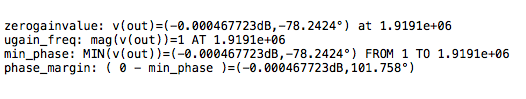
However, a frequency plot shows that gain spike showing up again, with 180p on the emitter res. It's showing its ugly head with the max at 2mhz and well above unity gain.
Weird, with a phase margin that high.
But all we have left are some small oscillations at crossover and not all over the place.
This points to using caps on the pre-drivers' emitter res of 180-220p values. TBD maybe...
However, a frequency plot shows that gain spike showing up again, with 180p on the emitter res. It's showing its ugly head with the max at 2mhz and well above unity gain.
Weird, with a phase margin that high.
But all we have left are some small oscillations at crossover and not all over the place.
Attachments


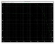
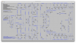
Here's something a little revealing.
To get rid of that gain spike at 2mhz, we can use the caps on the pre-drivers' C-B, which at 150p gives a smooth roll off and unity gain happens slightly before 2mhz.
The phase shift there is less than 80 degrees, giving over 100 degrees of phase margin.
And yet, having those caps on the C-B brings back the big oscillations.
This is with 100p on the 1k2 pre-drivers' emitter res.
Attachments

- Status
- Not open for further replies.
- Home
- Amplifiers
- Solid State
- grounded collector amp