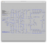
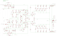
Just so we're in sync, I put in the 22 ohm resistors, and the 270s.
Ok, we're mostly in sync but not on the compensation caps.
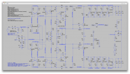
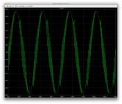
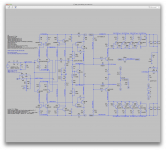
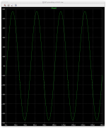
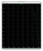
I put your latest values in to see what happens. Check the screenshots. We have oscillations. I'll tweak the caps to stop that...
I'd like to understand why the corner frequency moved down a little, and why the bizarre hook back on gain and phase got worse. Was it due to the front end mods, or removing the MJE340/350s? Or what else?
It's not from removing the mjes because they've already been removed a few steps ago and the more recent changes did alter those things.
So tweaking the front end did alter that.
For one thing, the height of that spike near 2mhz got smaller and happens lower and closer to unity gain now, after changing the front end.
Attachments
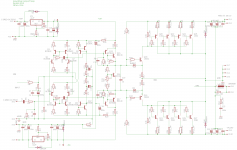
I'm curious what the effect of adding the feedback net I show on the attached is. I go from VAS to input. Tell me what you think.
Ok, I'll look at that next.
But I forgot to mention something earlier. While tweaking to stop oscillations, I ended up reducing the values of the resistors in parallel with the miller caps, from 220k to 180k. It really helped then. But I'll reset them for out next experiment.
Since the front end changed in the mean time, let's stay consistent.
I'm curious what the effect of adding the feedback net I show on the attached is. I go from VAS to input. Tell me what you think.
We have oscillations. With your values for compensation caps.
I'll run a couple of ac analysis with and without that extra feedback, so you can compare plots.
Attachments
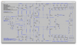
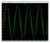
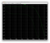
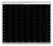
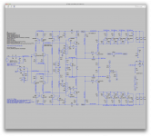
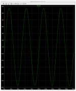
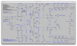
Ok it's not doing much.
Both plots are basically the same, as you can't tell the difference for with and without that extra feedback.
But this config oscillates.
I'll try to stop that.
Both plots are basically the same, as you can't tell the difference for with and without that extra feedback.
But this config oscillates.
I'll try to stop that.
Attachments
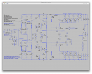
I haven't been able to stop all the oscillations yet. Only playing with the compensation caps and see what happens with and without that extra feedback to the in+.
One thing for sure, that extra feedback doesn't do anything.
I've had to go down to 1p on the miller caps, and not be able to stop oscillations completely, so I just disconnected it, and it makes no difference. Any value above 1p just continues increasing oscillations.
As far as the global feedback comp cap is concerned, I also had to drop it way down from 22p, but there is a sweet spot, below about 6p it will start increasing oscillations again, and same thing above about 7p.
I haven't tried again reducing the 220k in parallel with the miller caps, but I'm going to try that now. It did help before.
Attachments

Bringing down the 220k in parallel with the miller caps brings down oscillations somewhat, but they're not completely gone.
with such a tiny value for the miller caps, this is pointless and it does the same without them. 1p for caps is like the parasitic capacitance is layout, so no need to go down that low.
I think it's time to try out more advanced compensation.
with such a tiny value for the miller caps, this is pointless and it does the same without them. 1p for caps is like the parasitic capacitance is layout, so no need to go down that low.
I think it's time to try out more advanced compensation.
Attachments
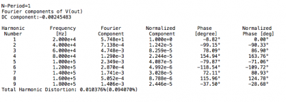
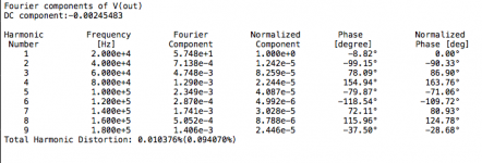
Here's a real improvement.
Without any tweaking so far. I just added this, left the global feedback cap as it was at 6p and arbitrarily picked the 2 comp caps, and bam! no more oscillations and thd down quite a bit:
Fourier components of V(out)
DC component:-0.00242276
Harmonic Frequency Fourier Normalized Phase Normalized
Number [Hz] Component Component [degree] Phase [deg]
1 2.000e+4 5.748e+1 1.000e+0 -9.12° 0.00°
2 4.000e+4 6.377e-4 1.110e-5 -99.46° -90.35°
3 6.000e+4 4.668e-3 8.122e-5 76.65° 85.76°
4 8.000e+4 1.253e-3 2.181e-5 149.16° 158.27°
5 1.000e+5 2.340e-3 4.072e-5 -85.29° -76.17°
6 1.200e+5 2.331e-4 4.056e-6 -107.73° -98.61°
7 1.400e+5 1.658e-3 2.884e-5 70.36° 79.48°
8 1.600e+5 4.513e-4 7.853e-6 100.78° 109.89°
9 1.800e+5 1.312e-3 2.283e-5 -45.22° -36.10°
Total Harmonic Distortion: 0.010141%(0.117721%)
(we're at 20khz here)
I'll tweak a bit and see what happens...
Attachments
We need an expert on compensation with insight I don't have. I've seen the RC net shown on the input collectors in older designs. Is it worth anything?
Yes, I've seen this too and used it before. Sometimes it helps, sometimes not.
And I agree we do need a compensation guru.
Here it is with slightly different cap values, but we can still detect a tiny hint of oscillation, however, curiously, the thd ain't too bad:
Fourier components of V(out)
DC component:-0.00240244
Harmonic Frequency Fourier Normalized Phase Normalized
Number [Hz] Component Component [degree] Phase [deg]
1 2.000e+4 5.747e+1 1.000e+0 -9.16° 0.00°
2 4.000e+4 5.933e-4 1.032e-5 -98.62° -89.46°
3 6.000e+4 4.621e-3 8.040e-5 76.54° 85.70°
4 8.000e+4 1.235e-3 2.149e-5 146.68° 155.84°
5 1.000e+5 2.352e-3 4.092e-5 -86.92° -77.75°
6 1.200e+5 2.170e-4 3.776e-6 -96.50° -87.34°
7 1.400e+5 1.645e-3 2.862e-5 71.37° 80.53°
8 1.600e+5 4.229e-4 7.358e-6 94.49° 103.65°
9 1.800e+5 1.258e-3 2.189e-5 -46.20° -37.04°
Total Harmonic Distortion: 0.010036%(0.141777%)

Lowering the caps some more brings thd down further, but won't stop all signs of oscillation.
So good comp work is required.
I'll test something else...
So good comp work is required.
I'll test something else...
We need an expert on compensation with insight I don't have. I've seen the RC net shown on the input collectors in older designs. Is it worth anything?
Apparently not so good for thd.
Attachments


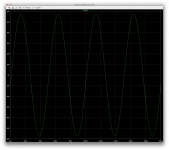
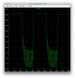
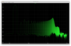
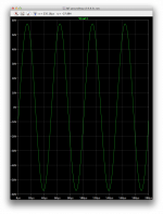
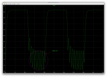
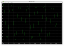
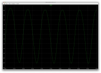
Here is the best I could do so far.
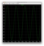
The sine wave looks almost clean, and the thd is somewhat ok.
We can see on the fft plot how much the high harmonics really go up, especially around that 2mhz zone.
We have something happening at about 2mhz, and finding out what this is about may help shed some light on this and compensate better.
Although the sine looks ok, check that square wave out...
Attachments
-
 Screen Shot 2016-11-28 at 3.48.39 PM.png136.9 KB · Views: 73
 -
 Screen Shot 2016-11-28 at 3.45.21 PM.png40 KB · Views: 69
 -
 Screen Shot 2016-11-28 at 3.45.01 PM.png537.3 KB · Views: 72
 -
 Screen Shot 2016-11-28 at 3.45.07 PM.png126.3 KB · Views: 77
 -
 Screen Shot 2016-11-28 at 3.45.10 PM.png485 KB · Views: 80
One thing of importance that I noted, while looking at the square wave, is the oscillation period seems to be about 1us, which would imply the oscillation is happening at about 1mhz, isn't it?
This isn't happening at the peak of that spike in gain where the big phase shift reversal is, at about 2mhz.
I forgot also to mention that the remaining visually detectable oscillations on the sine wave were basically gone once I added those caps on the drivers. I started them at 330p and went down from there.
Member
Joined 2009
Paid Member
I don't understand your comp scheme much but in my experience, for the CFP drivers, you want a simple Cdom, from base to collector of the 'master' device in each CFP compound pair.
I don't understand your comp scheme much but in my experience, for the CFP drivers, you want a simple Cdom, from base to collector of the 'master' device in each CFP compound pair.
This worked better than the simple one. I'm just trying things to compare what works and what doesn't, and how they compare.
I'm no comp expert, so I will defer to the gurus on this. We do need to figure this out. It's not right yet as it is.
What was important at first, was to at least get this thing running smotthly, and we're getting there. Now we must get rid of those pesky oscillations and get the margins right.
Spookydd says: This {split VAS compensation scheme} worked better than the simple one. I'm just trying things to compare what works and what doesn't, ... We do need to figure this out. It's not right yet as it is.
What was important at first, was to at least get this thing running smoothly, and we're getting there. Now we must get rid of those pesky oscillations and get the margins right.
I say: This is converging on a good solution. I agree, cure the oscillations. Their period of about 1us made me think, that's local to a stage, what about the MJE1503X drivers? They are a second VAS. Should we apply Miller compensation there, et voila, you were ahead of me. I note that the QSC 1700 has a huge cap there, 1.5nf in series with 47 ohms, if I read it right. We should have understood the significance of it earlier, but we got there. (When we used MOSFET drivers, there was the same oscillation, but we did not understand the significance then either). So, good progress, more understanding.
I am still focused on the DC operating points of the revised input section. My assumptions about the voltage out the the current mirror to drive the VAS base were on the order of 2v, it's 6+v. You increased the VAS emitter resistor to make it work, and it does. I'm curious if adding a resistor divider at the VAS base will bring that drive down. I tried 22k, just a swag.
Attachments
Their period of about 1us made me think, that's local to a stage, what about the MJE1503X drivers? They are a second VAS.
That's what I've been thinking, and that's why I also tried a small cap on them, and this did have a good effect on snuffing out most of the oscillations, but unfortunately not quite all.
Should we apply Miller compensation there, et voila, you were ahead of me. I note that the QSC 1700 has a huge cap there, 1.5nf in series with 47 ohms, if I read it right. We should have understood the significance of it earlier, but we got there.
I always hate to put overly big caps like this anywhere. Most of the time the bigger the cap, the more distortion anyway. I think there should be the "correct" size cap, and anything bigger than truly needed should be avoided.
Like I said earlier, my first attempt at a cap there was a 330p, and went down from that, not up. But what do I know? Maybe it could be what's needed, and that's why someone who's more the authority on this stuff should shed some light on this.
I haven't tried an R/C there, but maybe that'll work better than just a simple cap.
I did try this as you suggested earlier across the ltp legs, but that didn't do much, at least nothing useful, in that case.
I am still focused on the DC operating points of the revised input section. My assumptions about the voltage out the the current mirror to drive the VAS base were on the order of 2v, it's 6+v.
Yes, and it was even higher before that.
You increased the VAS emitter resistor to make it work, and it does. I'm curious if adding a resistor divider at the VAS base will bring that drive down. I tried 22k, just a swag.
How do you figure that?
You're not going to resistively attenuate are you?
One sure way to further reduce that drive is to lower even more those mirror loads.
Attachments
-
 Screen Shot 2016-11-28 at 9.40.42 PM.png503.7 KB · Views: 73
 -
 Screen Shot 2016-11-28 at 9.40.52 PM.png143.8 KB · Views: 70
 -
 Screen Shot 2016-11-28 at 9.41.07 PM.png38.7 KB · Views: 60
 -
 Screen Shot 2016-11-28 at 9.43.09 PM.png278.3 KB · Views: 59
 -
 Screen Shot 2016-11-28 at 9.43.36 PM.png267.3 KB · Views: 55
 -
 Screen Shot 2016-11-28 at 9.44.20 PM.png252.3 KB · Views: 60
- Status
- Not open for further replies.
- Home
- Amplifiers
- Solid State
- grounded collector amp