Reduce NFB resistors to 22k, or even 10k. Must center.
Reduce Vbias bottom divider resistor to zero temporarily.
Still won't center on its own.
But for reflection, what is now setting the gain there, since the previous feedback res are gone and were setting the gain, what is?
If that gain is somehow too high, perhaps that could explain why a slight imbalance at the vas could end up floating the rail all the way...
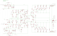
Attachments

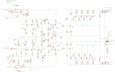
Spookydd said: Since it doesn't self center, I added the divider feeding the in- again, and got it biased and centered.
The bias spreader needs to spread nearly 2V, since we have already over 400mV on each of the pre-driver's emitter res.
Fairly centered, but not without forcing a little on the in- input.
I say: We need this to center using NFB, not a manual trim. Goal at least. Hopefully the last change will do that. The capacitive feedback to the predriver instead of straight miller cap is experimental, but it brings in the behavior of the output transistors, so that's why. Cap should be larger, not sure how large. 1nf? Spice to the rescue.
There really is no need for the predriver. Took it out. Drop Vbias, increase VAS emitter resistors and decrease driver emitter resistors.
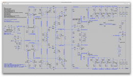
Attachments

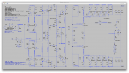
Spookydd said: Still won't center on its own.
But for reflection, what is now setting the gain there, since the previous feedback res are gone and were setting the gain, what is?
If that gain is somehow too high, perhaps that could explain why a slight imbalance at the vas could end up floating the rail all the way...
I said: I've been puzzling the same thing. The gain of the output stage is the NFB resistor divided by the source impedance, which is some function of the driver input impedance, the VAS output impedance and surrounding circuit pieces like the bias generator. Hard to compute, so I decided assume 1k source impedance and match with a 50k value and go from there. Take it as low as needed to center, although we know values in the 1k range affect vbias drastically. I was hoping something near 10k does it, but just for this exercise go as low as needed.
I am still bothered by the asymmetry of the output stage gain. A thought occurred, what if we make the driver one of the output types? Then perhaps the defects would cancel? I'll post that for discussion only.
Attachments

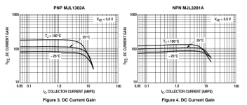
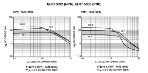
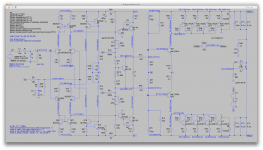
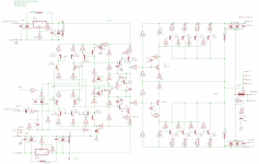
Why are the opposite sides so asymmetric? It's the drivers. The output transistors have similar flat gain curves up to 10A, beautiful. The drivers are great parts usually, but their beta varies a lot with collector current. So maybe using the output transistors as drivers is reasonable, if expensive. Like to see if that is worthwhile.
Attachments
Last edited:
We need this to center using NFB, not a manual trim. Goal at least. Hopefully the last change will do that.
Ok then, we'll try this way now, and then we'll switch the drivers afterwards.
The capacitive feedback to the predriver instead of straight miller cap is experimental, but it brings in the behavior of the output transistors, so that's why. Cap should be larger, not sure how large. 1nf? Spice to the rescue.
Yes, defintely! But we need to get the operating point fixed firts, before we let it rip in transient and start looking at compensation. We'll know more about this shortly, hopefully, if we can get that operating point right.
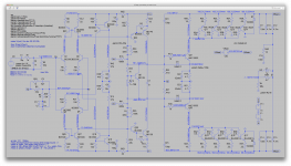
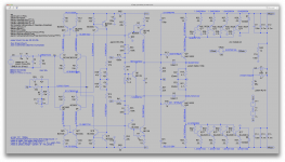
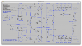
When I first ran the op after making those changes, I noticed how rather close to center it was, and that was with the feedback res at 22k to start from, and the bias currents in the O.Ds was strong at well over 1A.
But I gradually reduced the feedback res, as you can see on the first screenshot, and aiming for the proper bias, which does adjust, as the bias current decreases, the rails go farther away from center, not matter what value the feedback res have. They do have an influence, but too small to matter.
But I thought the first observation was interesting, so I went back again with 22k and ramped up the bias. It's totally off center with normal bias, and as we ramp it up, the center comes, and then beyond a point, that I haven't tried to pinpoint, the center starts again to falter.
Not sure where the sweet spot is, but it's somewhere not far above 1A25 (per O.D).
So I posted a couple of the screenshots highlighting this a little. I thought it was interesting and perhaps could bring a bit of insight.
I'll try switching those drivers now.
I know the imbalance can only be due to the difference in the models, but those rather reflect the reality and should be fairly faithful to the datasheets (come from cordell).
Attachments
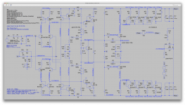
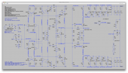
Why are the opposite sides so asymmetric? It's the drivers. The output transistors have similar flat gain curves up to 10A, beautiful. The drivers are great parts usually, but their beta varies a lot with collector current. So maybe using the output transistors as drivers is reasonable, if expensive. Like to see if that is worthwhile.
I think it's more than just how linear they are. Either parts have the same issues between the sexes, they're dissimilar. So although the MJLs may be more linear, we're getting the same behavior, as they are still different.
I took several shots to show how it evolves with the bias changing.
There is no point in dropping the values of the feedback res, as this won't fare any better than earlier.
Attachments
-
 Screen Shot 2016-11-30 at 10.39.58 PM.png696 KB · Views: 64
 -
 Screen Shot 2016-11-30 at 10.39.08 PM.png690.6 KB · Views: 53
 -
 Screen Shot 2016-11-30 at 10.38.38 PM.png691.4 KB · Views: 61
 -
 Screen Shot 2016-11-30 at 10.38.23 PM.png693.5 KB · Views: 56
 -
 Screen Shot 2016-11-30 at 10.37.58 PM.png689.8 KB · Views: 58
Just trying to think about this centering puzzle.
I'm wondering, how can we make it know what the center is?
A feedback may act on centering, but how could it know that whatever it finds is actually the center?
Since it's more than likely that real parts will be different between sexes, even though the same sex ones could be carefully matched, it's always quite hard to fully match them between sexes.
So if there is a dissymmetry built-in, I don't see how an automatic system could know where the center actually is.
I'm thinking only the human building it and adjusting the center would know where it needs to be.
Am I missing something?
I'm thinking that resistive dividers will have a hard time keeping their middle point truly at the center when there is a signal. At operating point, this could be forced by a trimmer to make the best match, but then while modulating, currents vary, and unavoidably the center will be alter at the divider's middle point.
I don't see any better way to create a middle point that wouldn't be temperature dependent either. Zeners would also have a similar issues anyway, with varying currents...
Just rambling....
I rethought the NF in the output again. I reduced the feedback resistor further, and increased the driver emitter resistor, to make it less dependent on transistor characteristics. So, another spin.
I suspect the same type of behavior would happen here if we increased the bias a bunch, there would likely be a sweet spot that could balance it out.
For one thing, it is not swinging all the way...
A thing that I find interesting is how close the bias currents are on both sides, while the symmetry is much less apparent at the drivers.
Attachments

Here is something maybe of interest.
I may be on to something, or not.
I simply added resistors to the rails from the driver bases.
I didn't calculate any values, just arbitrarily picked 33k, so maybe there is a better value, likely.
But look how much closer we get to balancing the rails this way...
I thought the bases would be "floating" a little much, because they don't have a very "solid" base for biasing, only the spreader.
Is this wrong?
Attachments
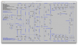
Reducing those resistors going to the rails and the 220 from the vas helps quite a bit.
I reintroduced a resistor in the spreader to have the range needed, and it adjusts better.
Now it's not really centered, but it does get much closer on its own this way.
Not sure if this will actually work once we give it a signal, but at least we get closer to an operating point.
Is this worth anything or not? Going the wrong way?
Attachments
I'm thinking that the 22k resistors to the rails are fine, but instead of centering the 4.7k resistor at NFB, that should be ground. The AC signal from NFB is equivalent to the AC rails voltage so it does nothing except add imbalance if tied to the emitters. Also, given the 22k resistors sourcing 3ma, the 4.7k resistor is a bit high; maybe 1k would be better, or even 470.
I think this configuration centered well before, but oscillated badly. Let's see how this does with different values.
I think this configuration centered well before, but oscillated badly. Let's see how this does with different values.
Attachments
I'm thinking that the 22k resistors to the rails are fine, but instead of centering the 4.7k resistor at NFB, that should be ground. The AC signal from NFB is equivalent to the AC rails voltage so it does nothing except add imbalance if tied to the emitters. Also, given the 22k resistors sourcing 3ma, the 4.7k resistor is a bit high; maybe 1k would be better, or even 470.
I think this configuration centered well before, but oscillated badly. Let's see how this does with different values.
I think this seems to work much better, and the dissymmetry seemed to get little influence from adjusting the bias, as opposed to what we've had lately. As when I was adjusting bias, the rails changed greatly accordingly, and not in a good way.
So this looks far better, although not quite centered yet.
Most of that dissymmetry there is highly likely to be caused by the model's differences, and this would be a reflection of reality, so we shouldn't try to make those models more agreeable and ideal.
Getting closer. Then we'll see about stability. But here we may want to revisit some of the ealier work, when it was rather close to stable, and the little left over oscillation probably could've been stopped by making use of those ferrite beads...
btw: I upped the bias trimmer's value, for more range.
Attachments
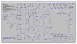
Looking good. I'm thinking some minor parts value changes will center it better. I think change the 1K base resistors on the drivers to 330-470. Change the 680k feedback resistors in the front end to 1M. Both of these changes increase DC gain and should help with centering.
Attachments
Looking good. I'm thinking some minor parts value changes will center it better. I think change the 1K base resistors on the drivers to 330-470. Change the 680k feedback resistors in the front end to 1M. Both of these changes increase DC gain and should help with centering.
I see you're going back to the regular drivers. Was that intentional? Or do we stay with the big power devices?
I tried each value change independently, to see which has the right effect and which way it goes. Unfortunately, oddly, it's having the opposite effect of pushing it farther out of center.
Changing the 680k feedback to 1meg worsens the centering by over 2V, while dropping them to 470k improves it by about as much. Curious.
Then droppping the the 1k base res to 470 and then 330 makes it go more out of center, and at 330 we're at almost 72V at the + rail, with the feedback at 1meg, and "only" almost 69V with them remaining at 680k.
By curiosity I dropped the feedback 680k to 470k, with the base res at 330, and we're at about 67V at the + rail.
I kept the 1302/3281 devices and their emitter res at 10ohms.
Do you want to try reverting back to the mje15xxx drivers?
By the way, I had noticed during other simulations that the mje15034/35 set was working better and more balanced. Maybe we could try those out...
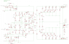
Unbelievable!
Opposite to what's expected, lowering the feedback 680k to 270k and increasing the 1k to 3k3 has brought it somewhat close to balance now.
I had to reintroduce a resistor in the bias spreader, instead of increasing the trimmer over 1k. It's almost to max range.
Trying to increase the driver base resistors further gains nothing more.
Attachments

I see you're going back to the regular drivers. Was that intentional? Or do we stay with the big power devices?
I tried each value change independently, to see which has the right effect and which way it goes. Unfortunately, oddly, it's having the opposite effect of pushing it farther out of center.
Changing the 680k feedback to 1meg worsens the centering by over 2V, while dropping them to 470k improves it by about as much. Curious.
Then droppping the the 1k base res to 470 and then 330 makes it go more out of center, and at 330 we're at almost 72V at the + rail, with the feedback at 1meg, and "only" almost 69V with them remaining at 680k.
By curiosity I dropped the feedback 680k to 470k, with the base res at 330, and we're at about 67V at the + rail.
I kept the 1302/3281 devices and their emitter res at 10ohms.
Do you want to try reverting back to the mje15xxx drivers?
By the way, I had noticed during other simulations that the mje15034/35 set was working better and more balanced. Maybe we could try those out...
Not passionate about the drivers, just thought the output devices did not improve things, so why waste money? I did have a thought about the outputs. The devices used by QSI are very slow, MJ15024/25. 3MHz Ft, instead of 30MHz. Later ones used MJ21193/94, also slow. Could that be a factor in stability? Once this is DC stable, we might swap in a pair of slow devices to see if that affects the situation for the better. Another area to explore... Oh, by the way, I have heard here on the board that those MJE15034/35 parts are vaporware, no stock anywhere. Do a search, you'll see what I mean. Bottom line, using the outputs as drivers did not change much, so either way is OK by me.
I am surprised that changing values worked the opposite of what I expected. I picked the 680k value arbitrarily to give a gain of 10 in the front end, just a round number. It turned out to be a good choice, so leave it. We don't care about centering of the front end alone, just wanted to avoid a trim pot. When we lower the gain, we increase distortion, so it's a tradeoff.
Odd that 1k seems a good choice, but just leave it. I would have thought that raising the DC gain of the front end would allow better centering, but no, it's worse, so something else is going on here. I'd say freeze this, and search for solutions to the stability issue.
I still don't understand the mechanism for the bizarre upswing in gain and phase shift at 2MHz. Where is it introduced? It seems fatal to stability, so we need to know. I changed the VAS from CFP to EF, no effect. I changed the drivers to outputs, no effect. Compensation tweaks it, but does not wipe it out. Where does this come from?? Remember when we used a MOSFET driver and things were much worse? That makes me think the problem could be in that area, the driver. It seems very sensitive to the performance of that part. What would happen if you put in a very slow driver, maybe use an MJ15003/4 model? I just want to vary things to see what affects the behavior. That would be a good clue.
Right now, I keep trying to visualize the mechanism for it, and I can't see it.
This is certainly a conundrum.
Not passionate about the drivers, just thought the output devices did not improve things, so why waste money?
Right. Sometimes it may be a good idea, and sometimes not. Those smaller TO220 drivers are easier to mount, smaller on the heatsink and cheaper, usually.
I did have a thought about the outputs. The devices used by QSI are very slow, MJ15024/25. 3MHz Ft, instead of 30MHz. Later ones used MJ21193/94, also slow. Could that be a factor in stability?
That's true. Sometimes using faster parts may be more trouble and it's better to use slower ones.
Once this is DC stable, we might swap in a pair of slow devices to see if that affects the situation for the better. Another area to explore...
Definitely worth a try. This may help with those pesky oscillations and keep it quiet.
Oh, by the way, I have heard here on the board that those MJE15034/35 parts are vaporware, no stock anywhere. Do a search, you'll see what I mean.
Really?
Not my experience. Maybe you haven't been looking in the right places.
Here's an example:
http://eu.mouser.com/_/?Keyword=MJE15035G
And I just looked at my own stock, and I do have 4 pairs of those boogers. Not quite that rare and can be found.
Perhaps less available than their 15032/33 counterparts.
Bottom line, using the outputs as drivers did not change much, so either way is OK by me.
Right, we didn't see any improvements that way.
I am surprised that changing values worked the opposite of what I expected.
Me too.
Odd that 1k seems a good choice, but just leave it. I would have thought that raising the DC gain of the front end would allow better centering, but no, it's worse, so something else is going on here. I'd say freeze this, and search for solutions to the stability issue.
Actually it centered better using larger than 1k on the driver bases. 3k3 got the best centering compromise, and going higher didn't do any better. But that was using the smaller values on the front end feedback.
I'll revert and see what we have.
If we move on to transient and stability, it will be done with the rails off center. But we'll see how this works out.
I still don't understand the mechanism for the bizarre upswing in gain and phase shift at 2MHz. Where is it introduced?
In fact this isn't only happening in this particular situation. I've seen this happen in a lot of others, and with certain compensation schemes, it can end up totally "absorbed" and basically disappear.
It seems fatal to stability, so we need to know. I changed the VAS from CFP to EF, no effect. I changed the drivers to outputs, no effect.
I've had this exact same gain spike in others totally different and didn't have the oscillations that would not go away. If this can be pushed far enough upwards in frequency and keep it down below unity gain, then it can be possible to obtain enough phase margin and keep it stable.
Actually certain kinds of configurations and part choices make this spike occur at very different frequencies, and sometimes the compensation "drowns" it enough so only a slight bump remains. (dominant pole??)
Compensation tweaks it, but does not wipe it out.
In some configs it does get wiped out.
Where does this come from??
I'd be curious to know. But from all the sims that I ran, I found that this is very much affected by the global feedback cap, so I'm not sure where it comes from.
Remember when we used a MOSFET driver and things were much worse? That makes me think the problem could be in that area, the driver. It seems very sensitive to the performance of that part. What would happen if you put in a very slow driver, maybe use an MJ15003/4 model? I just want to vary things to see what affects the behavior. That would be a good clue.
That could be worth a try. Those mje15xxx types are rather fast.
Right now, I keep trying to visualize the mechanism for it, and I can't see it.
This is certainly a conundrum.
Something will come up and we'll get this under control.
Posting a few shots with the input local feedback staying at 680k, and with the driver base res at 1k, 470 and 330. Which would be best to try transient sims with?
Attachments


How about that?
I tried with MJ15003/4 as drivers.
Had a harder time getting 100mA of bias with the drivers res at 470, so had to increase the res value at the spreader to get more range, but this isn't any better than with 330 at the driver bases.
Less than 3V left of rail imbalance that way.
Not only the mj15003/4 are slower, but they also must have much less gain at such low currents.
That would be robust, but will it work right? Will give it a whirl with transient and we'll see of it fares...
Attachments
- Status
- Not open for further replies.
- Home
- Amplifiers
- Solid State
- grounded collector amp