The main problem with the common emitter output stage, that the gain, and bandwidht are seriously changing as the output current change. Local feedback can reduce this problem.
Sajti
Sajti
Looking again at our last sims, with the caps on the feedback net still present, it actually pulls down all the way it can towards the low rail, with the small losses in vcesat and in the resistors, that's totally pegged there.
Then with the caps out of the way, it does the same thing all the way up in the other direction. The voltages are what they are because we're at the rails provided.
So it's not even trying to float somewhere in between, it goes all the way.
I tried to reunite the 2 halves just for kicks, and sure enough, with the power half being properly centered, the front end half tears it up.
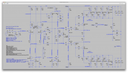
Ok, with everything in place (except taking out the caps on the feedback), the rails still fly way up there close to the high side, so I split it again to look at each part's behavior.
As you can see on the screenshot, I ended up keeping that centering pot to 500ohms, as lowering it would take out some current and make centering more tricky. Increasing its value brings up a little much bias current, and we don't even have the bias spreader hooked up yet...
With the 2 parts isolated, I can center the output part about alright and we have some 10mA of bias in each output already. Maybe a bit much...
Ok, we'll see what that does when we reconnect everything, but for now, the front end part is the one causing the imbalance.
With the caps still in the feedback network, we can see the imbalance, as it's pulling down.
With the caps taken out of the way, we have about the same drift but in the other direction. (2nd screenshot)
I don't think we have much to worry about any dc offset on the speaker output. There is no way it can come out even when the rails are all the way pulled in either direction. We have those big filter caps that are blocking any possible dc.
If you look again at earlier attempts, when it was pulling all the way up to the plus side rail, we still had hardly any dc on the output and I suspect it was more coming from the feedback from the front end...
If we can get the front part to self center better, I think we're on to something...
Try something to see if the front end centered. Ground the negative feedback input. What happens? Right now the front end is being upset by the negative feedback, even disconnected from the output stage. But I can add some local feedback to make it closer, why not?
We still need the output transistors to idle at 100ma, both sides. Disconnected from the front end, that's what we want to see. So try the pot at higher values until we get there. I guessed 500 ohms was low, 1000 too high, maybe somewhere in between like 750. Give it your best shot.
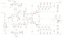
See attached schematic for numerous tweaks.
Attachments
Ground loops
All the output collectors will be grounded to the heatsink, which can be insulated from chassis. We still have the excellent thermal coupling to the heatsink. That isolates the output grounds, which can tie back to star ground.
The actual build will need this sort of thinking about every ground connection. It is manageable.
I'm wondering about the grounding for those grounded collector schemes.
Since all the output devices have their collectors directly connected to the heatsinks, they're automatically at the chassis, so what about ground loops?
What is there to watch out for as far as the other ground connections are concerned?
Of course doing some ground lifting for the signal ground and things like that can help, but then having the ground all around in the chassis with different parts of the amp connected to different points makes it tricky.
All the output collectors will be grounded to the heatsink, which can be insulated from chassis. We still have the excellent thermal coupling to the heatsink. That isolates the output grounds, which can tie back to star ground.
The actual build will need this sort of thinking about every ground connection. It is manageable.
Try something to see if the front end centered. Ground the negative feedback input. What happens? Right now the front end is being upset by the negative feedback, even disconnected from the output stage. But I can add some local feedback to make it closer, why not?
That's right, although the feedback is only picking up very little from the output, it's a good idea to try that. But unfortunately it didn't change anything.
We still need the output transistors to idle at 100ma, both sides. Disconnected from the front end, that's what we want to see. So try the pot at higher values until we get there. I guessed 500 ohms was low, 1000 too high, maybe somewhere in between like 750. Give it your best shot.
600 does it, but if we have that set the bias, then the spreader can't adjust it down once it's connected.
Attachments
Ok, I put the caps back on the feedback network, and since I had just grounded the 33k feedback resistor earlier, I left it there in place of that 10k extra one from your last mods.
I adjusted the power stages to about 100mA bias and centered it, so that works well enough.
And now seeing the tiny offset on the output having gone down much further, I suspect that little dc offset before was coming back from the front stage via the feedback res.
Why have a 10k resistor in parallel with the R/C series feedback network?
Making it 10k or 33k as shown doesn't change anything.
I just noticed that since I added those extra 100k resistors and the 220k local feedback ones, that one branch of the front end ltp now has almost no current going through, and its corresponding branch in the next ltp has the same issue, which may just be why instead of pulling all the way up it's now pulling down.
Keeping the front end and power stages still separate. At least we can see better what's going on that way.
Attachments
How about trying a completely symmetric approach to the front end, with dual ltp stages instead of cascading a couple?
Maybe a symmetric topo would better balance out.
Maybe a symmetric topo would better balance out.
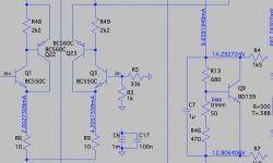
One more thing: I see the base of Q1 has a minus 25mV on it. Could that have anything to do with triggering a large swing?
Is there enough gain there to do that?
We don't have a global feedback working, so that input stage is open loop, and its gain should be rather high shouldn't it be?
Is there enough gain there to do that?
We don't have a global feedback working, so that input stage is open loop, and its gain should be rather high shouldn't it be?
Just to see what would happen, I just tried shorting to ground the in+ input from Q1's base, and that swapped everything. The branch of the ltp with no current have swapped, and instead of pulling all the way down, it's pulling all the way up.
That's right, although the feedback is only picking up very little from the output, it's a good idea to try that. But unfortunately it didn't change anything.
600 does it, but if we have that set the bias, then the spreader can't adjust it down once it's connected.
OK, so we put 600. It never needs to adjust down. QSC uses two diodes in series with a 50 NTC thermistor, so they never need it to go lower. Should be fine. But maybe that's the problem, the active bias spreader. Are the high currents from the output stage interfering with that ? I don't have a problem with two diodes plus a resistor or Schottky maybe. Leach used it, Citation 12 used it, bullet proof but a pain to mount.
Or do we have something wrong in the circuit that were missing, or in the model?? Could you show the whole circuit you are simulating? Let's solve this by checking each detail step by step. It's there somewhere. Or maybe one of the great minds of the internet will intercede?
By the way, in your pic of the output only did you show Femtovolts offset? Never seen that in my life. Keep that picture!
One more thing: I see the base of Q1 has a minus 25mV on it. Could that have anything to do with triggering a large swing?
Is there enough gain there to do that?
We don't have a global feedback working, so that input stage is open loop, and its gain should be rather high shouldn't it be?
I saw that. Seems high, but it's across 33k, so it's about a microamp of current (7.57575758e-7 A, I don't know how many FemtoAmps that is). Anyway, the point is equality of both inputs, if the other is at -25mv too then it's in balance. Grounding it was wrong, I should have said tie it to a -25mv source.
The front end gain is about one million times open loop. I just cubed a beta of 100, rough approximation, but it's probably between 100,000 and a million. Let's say 314159 times.
Ok, I put the caps back on the feedback network, and since I had just grounded the 33k feedback resistor earlier, I left it there in place of that 10k extra one from your last mods.
I adjusted the power stages to about 100mA bias and centered it, so that works well enough.
And now seeing the tiny offset on the output having gone down much further, I suspect that little dc offset before was coming back from the front stage via the feedback res.
Why have a 10k resistor in parallel with the R/C series feedback network?
Making it 10k or 33k as shown doesn't change anything.
I just noticed that since I added those extra 100k resistors and the 220k local feedback ones, that one branch of the front end ltp now has almost no current going through, and its corresponding branch in the next ltp has the same issue, which may just be why instead of pulling all the way up it's now pulling down.
Keeping the front end and power stages still separate. At least we can see better what's going on that way.
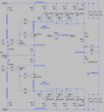
Show the circuit with currents. It's illuminating.
The 10k has no DC blocking cap, the divider does. So we have gain of 10 on DC, 33 on AC. QSC had gain of 6 on DC and 40 on AC. I did not think the 10k made sense either, but trying stuff.
Ok, I put the caps back on the feedback network, and since I had just grounded the 33k feedback resistor earlier, I left it there in place of that 10k extra one from your last mods.
I adjusted the power stages to about 100mA bias and centered it, so that works well enough.
And now seeing the tiny offset on the output having gone down much further, I suspect that little dc offset before was coming back from the front stage via the feedback res.
Why have a 10k resistor in parallel with the R/C series feedback network?
Making it 10k or 33k as shown doesn't change anything.
I just noticed that since I added those extra 100k resistors and the 220k local feedback ones, that one branch of the front end ltp now has almost no current going through, and its corresponding branch in the next ltp has the same issue, which may just be why instead of pulling all the way up it's now pulling down.
Keeping the front end and power stages still separate. At least we can see better what's going on that way.
Open loop The front end will swing to one extreme or the other, unless the inputs are exactly equal within femtovolts. It's like a comparator. Normal behavior open loop.
I get the feeling we're missing something obvious, but don't see it. I'll puzzle some more.
where's the .asc for the circuits? - should be able to attach them here, zip if using 3rd party models
Attach Files
Valid file extensions: asc bmp doc gif jpe jpeg jpg pdf png psd txt zip
OK, so we put 600. It never needs to adjust down.
In simulation that's just fine, but let's say this is going to be a real build, then perhaps some flexibility needs to be built-in for variations in part's performances and characteristics.
But maybe that's the problem, the active bias spreader. Are the high currents from the output stage interfering with that ? I don't have a problem with two diodes plus a resistor or Schottky maybe. Leach used it, Citation 12 used it, bullet proof but a pain to mount.
If it's a pain, for diyers that's not so nice. And I do like to have a good case like a TO126 to mount on a sink to sense heat, no diodes through some extra holes through the sink like the leach amp. That may work great in theory, but when building it, it can be a real pain.
Or do we have something wrong in the circuit that were missing,
That could be it.
or in the model??
And that too, but most parts not from ltspice's library, except for mosfets, are usually the good ones, if they're the most common used, like those from cordell's library.
It surely isn't excluded, if there is a bad model, it should be found.
Could you show the whole circuit you are simulating?
When I post a screenshot of this, most of the time it's a full window, so you see everything there is. Although what you don't see may be in question, the models. As they are loaded behind the scene.
Let's solve this by checking each detail step by step. It's there somewhere.
What do you have in mind?
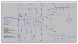
I try to have important and useful labels showing some currents and voltages, in strategic places. Maybe there are more that could shed more light. Any spot in mind?
Or maybe one of the great minds of the internet will intercede?
I know many are watching, so whoever sees us struggling can surely help.
By the way, in your pic of the output only did you show Femtovolts offset? Never seen that in my life. Keep that picture!
That's when the feedback was removed from the output, so there was nothing coming back from the input stage to raise it. Being all ground and caps, there is nothing to bring any dc there.
Like I said, I don't see how this amp could bring any dc at all to the speaker output. So once we remove all that can send a little something, the rails can't even do anything even if floated all the way, either way, the caps block it.
So an amp with blown OD can't damage speakers, just some transients can pass through, not dc.
Well, unless one of the big caps would fail shorted, but how often does that happen?
I saw that. Seems high, but it's across 33k, so it's about a microamp of current (7.57575758e-7 A, I don't know how many FemtoAmps that is). Anyway, the point is equality of both inputs, if the other is at -25mv too then it's in balance.
Well, I added a few more voltages, and of course removed that short. We definitely have Q3 way reversed biased, so of course no current goes through that branch, and this ripples through to the next ltp stage and almost nothing passes through the bias spreader.
I also added the voltage on the in- input, which shows the flagrant issue.
Grounding it was wrong, I should have said tie it to a -25mv source.
Well that was just a test to see how it would react. It was radical.
The front end gain is about one million times open loop. I just cubed a beta of 100, rough approximation, but it's probably between 100,000 and a million. Let's say 314159 times.
That's why the slightest dissimmetry can cause a large swing.
Most of those models, if not all, came from cordell's library, so since there aren't any other semiconductors used, all other models are ltspice internal.
So I doubt there is something wrong with those models.
We're missing something, but what?
Attachments
Show the circuit with currents. It's illuminating.
Sure, and we can do it all safely with no fear of burning anything up.
We can see far more in simulation than you could ever see with all kinds of meters while breadboarding.
No need to touch any parts until the design has been worked out. Then it can be breadboarded and further tested for real world, with most bugs having been hunted down before that.
The 10k has no DC blocking cap, the divider does. So we have gain of 10 on DC, 33 on AC. QSC had gain of 6 on DC and 40 on AC. I did not think the 10k made sense either, but trying stuff.
Sure.
But still, although this theoretically sets a dc gain, no dc can make it out anyway.
If I'm wrong, I'd like to see which path the dc can take to the speaker...
Open loop The front end will swing to one extreme or the other, unless the inputs are exactly equal within femtovolts. It's like a comparator. Normal behavior open loop.
I guess so. So separating the amp in half works out for the power half, but not for the front end. Maybe we can fake a load on the bias spreader that looks like the power end would to it, and do something to close the loop, and perhaps we can further troubleshoot this way.
I get the feeling we're missing something obvious, but don't see it. I'll puzzle some more.
It could be something small, but maybe this idea of closing the loop around that front end could help seek what's going on..
where's the .asc for the circuits? - should be able to attach them here, zip if using 3rd party models
Of course.
Attached.
It's just that we've been making so many and it's faster to just grab a snapshot, I didn't take the extra time to gather stuff and zip it up.
The models files contains more models than this sim uses, but that's because I keep using the same file for many sims and just add more models when needed.
I don't know if the mosfet models are any good.
The bjts should pretty much all be from cordell.
Attachments
I get the feeling we're missing something obvious, but don't see it. I'll puzzle some more.
I do not see it. So, simplify. Is the bias spreader goofy? QSC used plain old diodes, so... try that. So the attached has diodes. If this does not pan out, simplify more.
Attachments

- Status
- Not open for further replies.
- Home
- Amplifiers
- Solid State
- grounded collector amp