Please re-read the 'best initial settings' section on the oscilloscope page of the site (page 73).
Sorry, just wanted to show both sides with the same scope settings and these was the best setting as it could get.
Last edited:
Is this the high side or the low side?
If this is the high side and you're absolutely sure that there is no secondary voltage, jump the high-side source leg to the secondary ground. You can use a low value (1-10 ohms, 1/4w resistor) if you want to offer a bit of protection in case there are other problems.
If this is the high side and you're absolutely sure that there is no secondary voltage, jump the high-side source leg to the secondary ground. You can use a low value (1-10 ohms, 1/4w resistor) if you want to offer a bit of protection in case there are other problems.
If am not mistaken, its low side, but why its "low"?
I will later recheck with better resolution.
I will later recheck with better resolution.
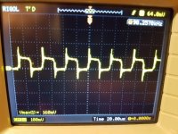
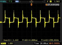
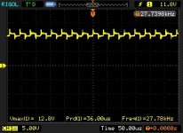
So i scoped it again.
Scope settings: ground from the amplifier GND terminal, probe 1X
Gate measurements.
First picture from the banks which is closer to rectifiers, should be high side,
the second one is from the low-side.
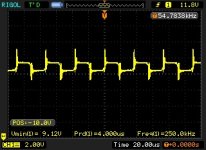
Third picture is also low side, BUT vertical position of the scope is -10.0V
Scope settings: ground from the amplifier GND terminal, probe 1X
Gate measurements.
First picture from the banks which is closer to rectifiers, should be high side,
the second one is from the low-side.
Third picture is also low side, BUT vertical position of the scope is -10.0V
Attachments
Last edited:
Did you ground the source leg of the high-side FETs?
What frequency drive signal are you driving into the amp?
What frequency drive signal are you driving into the amp?
I tried to drive 100Hz and 50Hz - there was no difference in output transistor gate drive signal.
I grounded only one transistor from one group - there was no difference in measurements.
I grounded only one transistor from one group - there was no difference in measurements.
Do you see the drive signal (sine wave, possibly clipped sine wave if driven too hard) on any of the pins of the center connector on the driver board?
Here is what i have on driverboard input, its not cliped, because its driven to hard, its just whats comes in on board. From rca its clean signal.
Another thing. If i ground scope probe on secondary ground (speaker output minus terminal), i dont see any oscillation signal on gates from output transistors.
Second picture. About grounding source leg, transistors are not grounded yet, here is signal on all output transistors source legs (amplifier main ground terminal as reference)
Attachments
Last edited:
Do you see the same distorted sine wave at the input to the driver board if you use the secondary ground?
Sorry that again i didnt mention grounding.
Picture before was grounded on secondary ground.
Here is the picture when probe is on amplifier main ground (the same input pin on drivercard). If i drive sinus signal in amp, i see that signal is oscillating in driven frequency.
Both measurements done when driver board is out of main board, because i have problem to probe while its in. Should i measure while its in?
Attachments
Last edited:
The first thing I think we need to do is get a clean sine wave to the driver board. Set the gain and crossover fully clockwise and the subsonic filter fully counter-clockwise. Does that help?
I tried different crossover, gain settings and it didnt help to clean sinewave top waveform.
I can confirm that all opamps have +/- 15V. Secondary ground as reference.
I can confirm that all opamps have +/- 15V. Secondary ground as reference.
You need to find where the signal becomes distorted. Follow it from the back of the RCA jack through the op-amps in the preamp circuit.
I started to rembember that before i removed rectifiers I tested and had good sine wave from pre-amp board.
Here what i have done:
Removed all output transistors. Reinstalled rectifiers.
And this is the input at driverboard (drivercard is removed), clean sinewave signal. I just removed outputs and reinstalled rectifiers.
Edit. While outputs are out of board, i now tested the drive signal, low-side gate drive is the same as before, high side i didnt check, because i did not install the 9v battery for 21844.
Attachments
Last edited:
Take the scope out of auto mode. Set the timebase to 2ms. Set the coupling to AC. Set the v/div to 10.
Post photos of the drive signals.
Post photos of the drive signals.
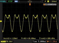
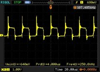
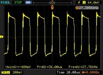
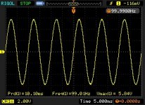
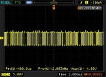
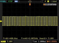
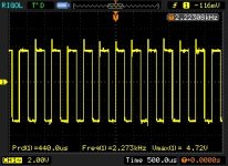
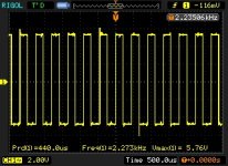
AC coupled. Scope ground on negative speaker terminal. high side with 9v battery.
First two pictures with 5V and 2ms settings, and last two with 2V and 500us.
1th and 3th is high side.
2th and 4th is low side.
First two pictures with 5V and 2ms settings, and last two with 2V and 500us.
1th and 3th is high side.
2th and 4th is low side.
Attachments
Last edited:
- Home
- General Interest
- Car Audio
- Ground Zero 10kXSPL