Found open 3W resistor which was connected between output + and -, soldered 10k, powered with both 21844 enabled and it blowed output transistors. The transistor plastic case flew away. The power supply was limited to 6amps.
Thats expensive.
Thats expensive.
Current limiting doesn't work on an amplifier that charges the rail caps then enables the output transistors. I don't know if that applies to this amp.
For some amp, you can force the output to be enabled at all times. That allows the current limiter to be more effective because there is no energy stored in the capacitors.
If the 12v regulator has dedicated windings on the transformer, you may be able to check the drive signals with the FETs in the board. Removing the rectifiers would prevent the caps from charging.
The high-side would likely need a supply on the 21844s. I use a 9v battery.
If the 12v regulator has dedicated windings on the transformer, you may be able to check the drive signals with the FETs in the board. Removing the rectifiers would prevent the caps from charging.
The high-side would likely need a supply on the 21844s. I use a 9v battery.
I am just thinking how to and what to do now.
Remove outputs and test drive signal after rebuilding again output driver card?
Why it didnt go in protect while each 21844 was disabled.
And it will work when only 4 of the outputs fets will be installed, one per group? Dont want to blow them all.
Remove outputs and test drive signal after rebuilding again output driver card?
Why it didnt go in protect while each 21844 was disabled.
And it will work when only 4 of the outputs fets will be installed, one per group? Dont want to blow them all.
Last edited:
I would test without the rectifiers. That should be safe. Yes, after rebuilding the driver board.
I don't know why it didn't fail with only one driver IC enabled. An intermittent problem like an intermittently shorted inductor may make troubleshooting difficult. You need to go through all tests with only one IC enabled at a time. Push/pull/twist inductors...
If the problem is an over-current fault, having all of the FETs in the circuit will make the outputs more likely to survive.
I replaced 21844, all parts are soldered in except output transistors.
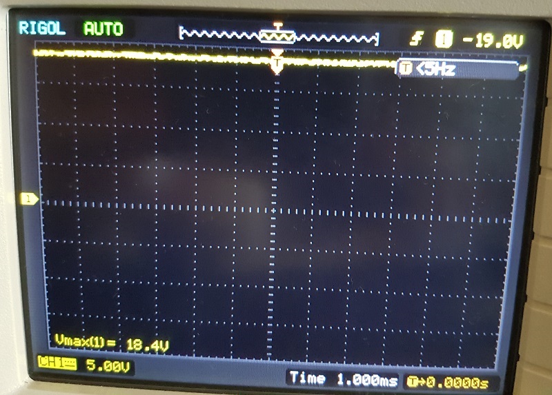
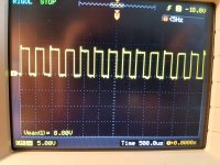
This is the output low-side gate:

But the high-side gates are without drive signal (both banks). The drain have positive rail signal.
The picture of the drain
This is the output low-side gate:
But the high-side gates are without drive signal (both banks). The drain have positive rail signal.
The picture of the drain
Attachments

Or there will be no high side drive signal, because there is no carrier/oscillation?
I did not supply 21844 high side with 9v battery. Thats why there is no high side drive signal... For those who dont know how to do it and also reading:
Perry:
I did not supply 21844 high side with 9v battery. Thats why there is no high side drive signal... For those who dont know how to do it and also reading:
Perry:
The high side supply is generated by the pulses from the output transistors. Since you're testing with the outputs out of the circuit, there will be no supply voltage for the high-side drive circuit. Pins 11 and 13 are the supply pins for the high-side.
Connect a 9v battery with the negative terminal on pin 11 and the positive terminal on pin 13. I'd suggest inserting a 1 ohm 1/4w resistor in series with the battery in case there is a problem that tries to drive voltage back into the battery (or any other problem that could cause the battery to overheat).
Drive a signal into the amp. If you drive the amp with a strong 100Hz sine wave, you should see a 100Hz square wave on the gates of the high and low side FETs. The square wave should have rising and falling edges that are essentially perfectly vertical.
Also, what glue to do You use for securing parts like output chokes?
Glue needs to be flexible, easy to remove if needed and can stand higher temperatures.
Glue needs to be flexible, easy to remove if needed and can stand higher temperatures.
The method of securing inductors and transformers varies (you can't always use adhesive alone). For the adhesive, I typically use Goop or E6000. I've started using the following adhesive. It tends to set up quicker than the two previously mentioned.
https://www.walmart.com/ip/Aleene-s-Platinum-Bond-Super-Fabric-Textile-Adhesive/17299866
I don't know if any of these are available where you are.
They are easy to remove in some aspects but don't expect to remove it from between windings.
https://www.walmart.com/ip/Aleene-s-Platinum-Bond-Super-Fabric-Textile-Adhesive/17299866
I don't know if any of these are available where you are.
They are easy to remove in some aspects but don't expect to remove it from between windings.
Just removed output chokes and i didnt found any visible shorts, soldered them in and secured with e6000.
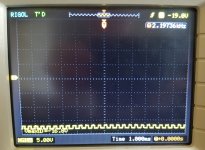
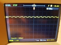
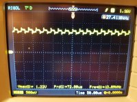
Here are the pics from high side and low side, all 4 bank drive signal looks the same. Scope probe set to 10x. No transistors and capacitors connected.
Here are the pics from high side and low side, all 4 bank drive signal looks the same. Scope probe set to 10x. No transistors and capacitors connected.
Attachments
I wouldn't expect the high-side drive to be at the positive rail. What are you using to supply voltage to the high-side of the driver IC?
Do you possibly have a solder bridge between the drain and source of the high-side FETs?
Confirm with a meter.
Confirm with a meter.
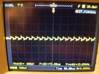
Right now cant check the measurements, but picture maybe confusing, because scope V axis is scrolled up to see low-side.
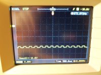
Here is the measurement of the high side gate (9v battery connected at 21844) with scope probe set to 1x
Attachments
Last edited:
Confirmed all with meter, there is no shorts.
I have in stock 4pcs IRFP460 - can they be used for testing purposes?
I have in stock 4pcs IRFP460 - can they be used for testing purposes?
Is that the only part you have or are you trying to find something that you can use so you don't blow the correct FETs?
I think I'd remove the rectifiers and check the drive signals with the output FETs installed. The loading of the FET gate capacitance will affect the drive signal. The full load of the correct FETs is better than testing with a partial load of FETs.
I think I'd remove the rectifiers and check the drive signals with the output FETs installed. The loading of the FET gate capacitance will affect the drive signal. The full load of the correct FETs is better than testing with a partial load of FETs.
I am saving correct fets.
Best way will be install all 460lcs in place and test it without rectifiers? Thats how i will try.
Best way will be install all 460lcs in place and test it without rectifiers? Thats how i will try.
- Home
- General Interest
- Car Audio
- Ground Zero 10kXSPL