I have this amplifier and I am a bit lost.
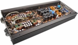
It came in with blown outputs, their drivers. Outputs was IRFP460LC, their drivers was KTA1715 and KTC2814.
There was capacitor 1.2uf 250vac with broken, burned leads, replaced with 1.2uf 400Vdc. One lead of the output choke leads was desoldered from the main board, i think it cracked from vibrations and came off.
I had a great deal some time ago and I replaced outputs with IRFP360LC, gate resistors i left the same, drivers I replaced with BD140, BD139.
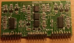
I replaced all IC's of the output driver board. All sot23 transistors on driver board tests fine.
The problem is that, when amp is powering up, relay turns on and off - goes in protection. I can confirm that, before protection there are DC on the output terminals.
When output driver board is pulled off, amplifiers powers on:
The power supply is working and I do get +/- rail voltages, I confirmed, that 5V,12V and 15V regulators are working. There are no DC voltage from preamp board.
Could be there still a problem in driver card or should i orderd original driver/outputs?
Sorry, i dont have right now photos with main board, i can photo it in monday.
It came in with blown outputs, their drivers. Outputs was IRFP460LC, their drivers was KTA1715 and KTC2814.
There was capacitor 1.2uf 250vac with broken, burned leads, replaced with 1.2uf 400Vdc. One lead of the output choke leads was desoldered from the main board, i think it cracked from vibrations and came off.
I had a great deal some time ago and I replaced outputs with IRFP360LC, gate resistors i left the same, drivers I replaced with BD140, BD139.
I replaced all IC's of the output driver board. All sot23 transistors on driver board tests fine.
The problem is that, when amp is powering up, relay turns on and off - goes in protection. I can confirm that, before protection there are DC on the output terminals.
When output driver board is pulled off, amplifiers powers on:
The power supply is working and I do get +/- rail voltages, I confirmed, that 5V,12V and 15V regulators are working. There are no DC voltage from preamp board.
Could be there still a problem in driver card or should i orderd original driver/outputs?
Sorry, i dont have right now photos with main board, i can photo it in monday.
Attachments
Last edited:
It should be safe to short pin 2 to pin 5 to keep the driver off but let me try it on a smaller amp I have here before you try it.
That and adding a local feedback resistor to the TL072 should allow you to check everything up to the driver IC input. It will be a couple of hours before I get back to the shop to try it.
That and adding a local feedback resistor to the TL072 should allow you to check everything up to the driver IC input. It will be a couple of hours before I get back to the shop to try it.
Tried to check voltages without output driver card, ground as reference:
1: -112V
2: -163V
3: -163V
4: -151V
5: 5V and falling
6: 0
7: 0
8: -164V
9: -164V
10: -106
11: swings from 0 to +1.3V
12: -4.9
13: 0
14: 0
15: 5V
16: 0
17: -164V
18: 0
19: 0
20: 1.7V
21: -152V
22: -164V
23: -164V
24: -107
1: -112V
2: -163V
3: -163V
4: -151V
5: 5V and falling
6: 0
7: 0
8: -164V
9: -164V
10: -106
11: swings from 0 to +1.3V
12: -4.9
13: 0
14: 0
15: 5V
16: 0
17: -164V
18: 0
19: 0
20: 1.7V
21: -152V
22: -164V
23: -164V
24: -107
I checked, with driver board in, while amp is powering up, before protection, there are negative 130V on output terminals.
Is it how it should be? - when output driver card is out, amp powers up, but one half of the output fets on the gates reads negative 160V and other side on the gates 0V?
Let me check something on an amp that I have here.
I don't have the voltage or pin configuration for that board so I cannot give any specific answers for those.
I don't have the voltage or pin configuration for that board so I cannot give any specific answers for those.
On a much smaller amp, I shorted pin 2 of the 21844 to the negative rail (pin 5). This was done by shorting across the small SMD capacitor that was in front of pin 2.
This completely shut the amp down. There was no DC on the output and the relay engaged.
The amp was driven with an 80hz signal. The output of the TL072 was distorted but good enough to drive the LM211. The output of the LM211 had a square wave that swung ±5v from ground. The signal appeared at the input of the 21844 as an 80hz square wave that swung from the negative rail to 12v above the negative rail. That confirmed that everything up to the IC was OK.
This should be usable on your amp as well but be aware that I've never tried this on any other amp.
This amp has only 1 21844. I would short both initially to see if the 130v went away on the output.
Then check the drive signal to confirm that it's reaching both ICs.
Then check the drive signal to confirm that it's reaching both ICs.
Amp powered up with no DC on the outputs!
There is drive signal for the output fets but its noisy. Drove 100Hz signal, but one the input of the 21844 (pin1) was only negative voltage (didnt check exactly how much with scope).
Edit: i scoped the driver card and saw ~100hz square wave on the Q3 base.
There is drive signal for the output fets but its noisy. Drove 100Hz signal, but one the input of the 21844 (pin1) was only negative voltage (didnt check exactly how much with scope).
Edit: i scoped the driver card and saw ~100hz square wave on the Q3 base.
Last edited:
I don't know what Q3 does on this board. On other boards, the output of the LM211 drives an emitter follower pair. From there the signal goes through a resistor to the emitter of transistors marked 2D. The collector drives the IC. The base is grounded.
If signal is OK on one IC, the emitter follower pair is likely OK and the problem is between the pair and the input of the IC.
If signal is OK on one IC, the emitter follower pair is likely OK and the problem is between the pair and the input of the IC.
So the problem is on the output driver card?
I will try to draw schematic so it will be easier to troubleshoot.
I will try to draw schematic so it will be easier to troubleshoot.
You already have most of it on the generic class D - Type 3 page of the tutorial. Print that out and mark it with the differences.
Amplifier now is working!
There are another little problem, right after relay engages, there are little DC spike on the output terminals, its audible when subwoofer is connected, otherwise amp is working.
I am thinking maybe to increase the turn on delay?
Grounding rca shield in different spots - not helping.
There are another little problem, right after relay engages, there are little DC spike on the output terminals, its audible when subwoofer is connected, otherwise amp is working.
I am thinking maybe to increase the turn on delay?
Grounding rca shield in different spots - not helping.
Look at the signal before the relay so you can see the output of the amp before the relays engage. If the amp has signal on both the positive and negative speaker terminals, you'll need to check both.
Long story short.
Amp blew again, not sure why.
I didnt have time, but I managed to do:
I rebuilded the output driver card, replaced all ICs, some of the transistors also.
Replaced output transistors and their drivers (bd139, bd140). Gate resistors all are within tolerance.
The situation is the same as before, there is DC on the output (i measured before relay) and it goes immediately in protect right after (!) relay engages. When measuring, the DC voltage, its falling to 0, but its not able to reach 0 before relay engages.
I disabled 21844 by bridging 2 and 5 pin. Checked all drive signals from tl072=>0211=>21844 and they are like Mr. Perry mentioned - so far so good.
But the problem still exist.
The original output drivers was KTA1715 and KTC2814, I replaced with BD140, BD139.
As Perry mentioned many times before, that BD140, BD139 may not work in output section for class D. Could it be, that the problem is drivers?
I dont know, that else can lead to DC spike which falls. I did check all components on output driver card and don't think that i miss some bad one.
Last edited:
Forgot to mention, before protection i can hear click sound from area of the output inductors. Could that indicate short?
I don't think the BD drivers were a problem in this amp. The originals were rated for less voltage and voltage is generally what causes drivers like the BD139/140 to fail in the output stage.
When you hear a click in an inductor or transistor, it's sometimes due to a spike in current flow through it.
Enable one driver IC at a time (having only one enabled at any time). Does the problem seem to be associated with one IC/drive circuit?
When you hear a click in an inductor or transistor, it's sometimes due to a spike in current flow through it.
Enable one driver IC at a time (having only one enabled at any time). Does the problem seem to be associated with one IC/drive circuit?
- Home
- General Interest
- Car Audio
- Ground Zero 10kXSPL