I have actually considered connecting the ground plane at signal input shield
instead of star ground, to maximize EHF skinning.
This is what Ralph Morrison recommends, but few do that.
I was thinking more about examples that reflect the name of the thread
Ground Plane for Power Amplifiers
Ground Plane for Power Amplifiers
That would definitely be a good start. I think the main question would be, is there any need to divide the ground plane between signal and power sections as long as it was only connected to the circuit at star ground. I can't come up with a reason why not, and if that is true then cutting up the plane could actually just increase inadvertent antenna and RFI issues.
An easy way to test would be to make a single-sided SMD amplifier with very low THD, and use a separate board as the ground plane, so you can test the amp with and without the ground plane.
An easy way to test would be to make a single-sided SMD amplifier with very low THD, and use a separate board as the ground plane, so you can test the amp with and without the ground plane.
I do not like to repeat the theories. In term of very thin traces on PCB’s there are sometimes very complicate to kill the 50Hz noise, if any coupled high value capacitors are near output transistor. It is a good measure to put 1mm2 copper over delivery traces on board for lower impedance. This is very hard to find, but after those many years R/D, I fix this problem, now anytime I aware of this capacitors. Any good smooth voltage is enough for high quality output without any capacitors in neighborhood of output transistors.
Primary solution is ever very fast and quality transit scheme (lower applicable fastness is about 300V/usec), if you are able to raising the fastness of transit frequency speed inside PCB, mean in input be about 1mA in voltage buffer, in translator to voltage swing about 3mA, then tracing to drivers with about 7mA (could I preferring 2SA970 and complementary 2SC2240 for first two stages, low noise, audio and high voltage capable, without separate driving an output voltage), at the end low signal section about 30mA on drivers, with adequate material (BD139/140). I am every time using, depend on type of output maybe optimal 150mA on MosFet, Analog or other kind of output transistors for cancelling and overhaul input capacitance. In my case I every time using compound type of output in term of carefully studied Matti Otala proposals. It is also very good measure, if separate input voltage from low level signal with GP and maybe input signal ground from star ground point with 10E resistor with jumping option, sometimes this not work and you have to realize the solution in site. I am in R/D this kind of current feedback schemes from 1985 with excellent results, but not commercial.
Primary solution is ever very fast and quality transit scheme (lower applicable fastness is about 300V/usec), if you are able to raising the fastness of transit frequency speed inside PCB, mean in input be about 1mA in voltage buffer, in translator to voltage swing about 3mA, then tracing to drivers with about 7mA (could I preferring 2SA970 and complementary 2SC2240 for first two stages, low noise, audio and high voltage capable, without separate driving an output voltage), at the end low signal section about 30mA on drivers, with adequate material (BD139/140). I am every time using, depend on type of output maybe optimal 150mA on MosFet, Analog or other kind of output transistors for cancelling and overhaul input capacitance. In my case I every time using compound type of output in term of carefully studied Matti Otala proposals. It is also very good measure, if separate input voltage from low level signal with GP and maybe input signal ground from star ground point with 10E resistor with jumping option, sometimes this not work and you have to realize the solution in site. I am in R/D this kind of current feedback schemes from 1985 with excellent results, but not commercial.
I was thinking more about examples that reflect the name of the thread
Ground Plane for Power Amplifiers
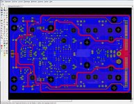
Well, here is a little amp pet project in which I put all traces on the top layer and a solid ground on the bottom to try out this highly controversial subject.
So who wants to throw the first stone ? 😀
Edit: Sorry for that image glitch.
Attachments
Last edited:
I can only view the image if I right-click->open in new tab. Can't really see how the ground plane is used anyway though.
I am planning a SMT amplifier PCB with a full ground plane on one side of the PCB.
After reading this thread it is still very unclear whether it's a good or bad thing to do.
Any recent/updated thoughts on this topic?
Thanks.
After reading this thread it is still very unclear whether it's a good or bad thing to do.
Any recent/updated thoughts on this topic?
Thanks.
It depends on the circuit.
If lots of low power stuff then a solid ground plane is good.
If some very high power parts then I would star ground it.
Or maybe selective ground planes but keep high and low power grounds apart.
If lots of low power stuff then a solid ground plane is good.
If some very high power parts then I would star ground it.
Or maybe selective ground planes but keep high and low power grounds apart.
And then connecting them with a thin trace?Or maybe selective ground planes but keep high and low power grounds apart.
- Home
- Amplifiers
- Solid State
- Ground plane PCB design for power amps