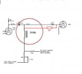
I'm assuming the 'top' of the choke is the bias side? So the cap would be installed as in the new drawing? And what value?
The bias side is the lower side in the drawing, the side closest to the ground as it appears on the screen. Why would you assume it is the top?
And remember if you use an electrolytic cap here attach the positive to ground as your bias supply has a negative voltage.
Its going to form a high pass with the 15k is that right? And if so a 5uf cap should give me a -3db of about 2.1hz, sound good?
Low pass, not high pass. Make sure that the time constant on the B+ is significantly longer than the bias supply decoupling cap otherwise you will run without bias during some portion of warm up which is never a good thing.
If you are using a 5AR4 or other indirect heated rectifier for B+ you should be fine.
Film cap is fine.
If you are using a 5AR4 or other indirect heated rectifier for B+ you should be fine.
Film cap is fine.
The bias side is the lower side in the drawing, the side closest to the ground as it appears on the screen. Why would you assume it is the top?
hello !, seen your blog with schade fb
i´d like to implement on a bit dusty pair 4-125a´s; some recommedations?😉
Kevin, I have an NTC thermistor on the B+ It takes about twenty seconds before the B+ comes up. I have a 4.7uf 250 volt Dayton crossover cap I was thinking of using that.
By time constant is that the time it takes for the cap to charge?
hpeter, that Schade fb push pull amp is on hold till I get this damn AD1 thing done. When I finish that one I'll contact you.
By time constant is that the time it takes for the cap to charge?
hpeter, that Schade fb push pull amp is on hold till I get this damn AD1 thing done. When I finish that one I'll contact you.
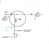
i´d add cap from choke bottom to gnd (?)
yes, in order to put the lower end of the choke at AC ground....
in any amp, especially tube amps, there are lots of AC grounds....
By time constant is that the time it takes for the cap to charge?
http://www.electronics-tutorials.ws/rc/rc_1.html
I was thinking of using a non-plorized film cap?
why? but of course you can if you want to...
hello !, seen your blog with schade fb
i´d like to implement on a bit dusty pair 4-125a´s; some recommedations?😉
I recommend you do it. 😉 That would be an awesome amp. If you do it with a p-channel fet like I did, you have to be a bit careful how you choose the DC conditions, since it is hard to find p-channel parts with high voltage ratings, and you might need an n-channel fet inside the loop to drive the grid if you want to go in the positive grid region.
If you start a thread on it, I'll show up. (If I don't, PM me and bring it to my attention.)
Hey All, on this bypass cap what kind of voltage is it likely to see? Would it see the output voltage of the 6SN7?
Also, I thought a non-polarized film cap might be in order because it will see negative bias supply voltage and positive ac voltage from the preamp tube's signal. And also the grid current I'm trying to bleed off will be positive won't it?
Also, I thought a non-polarized film cap might be in order because it will see negative bias supply voltage and positive ac voltage from the preamp tube's signal. And also the grid current I'm trying to bleed off will be positive won't it?
Last edited:
Just the negative bias voltage.... The AC swing at that end of the choke will be insignificant due to the reactance of the choke as compared to the reactance of that capacitor. I have not thought out the grid current issue, but if there is significant grid current in the AD1 then you need either an interstage transformer and a much beefier driver tube or tubelab's power drive circuit.
Have you verified that the driver stage can linearly swing the required drive voltage without the AD1s in their sockets? (I think with some margin you need about 90Vpk)
Have you verified that the driver stage can linearly swing the required drive voltage without the AD1s in their sockets? (I think with some margin you need about 90Vpk)
Before doing some tests, did you measure the resonant frequency of such a choke and the stray capacitances? Whit such an inductance, resonating with stay, plus Miller capacitance, I believe the choke will be useless in the thousands of hertz.
I have done similar things, the choke's inductive reactance appears in parallel with the source impedance of the driver stage, in most cases I have been able to achieve a flat response over a 20Hz - 20kHz at better than 1dB. This is a good solution where the cost of a good IT is prohibitive but a low dcr is required in the grid circuit. I rarely use this approach, but I have often used a choke load in the driver stage.
It sounds bad for me. doing some math, taking the 350H inductor, it will resonate at 10000Hz with only 0.7pF :-(
You need to take into account that it is shunted by the source impedance of the preceding stage. It's a parallel RLC with a low R relative to the inductor reactance. (Try it with an R of 10K or so and see what happens)
- Status
- Not open for further replies.
- Home
- Amplifiers
- Tubes / Valves
- Grid Chokes