Hello Zobsky,
I used the MCM 55-2421 8" woofer. The woofer is 87db and the Holliman cab seems to be that efficient.
I simply took the 10" plans and reduced the dimensions by 20% to come up with an 8" version.
In Room RTA with Pink Noise:
The scale on the RTA is 0 to 16k HZ.
Charlie
I used the MCM 55-2421 8" woofer. The woofer is 87db and the Holliman cab seems to be that efficient.
I simply took the 10" plans and reduced the dimensions by 20% to come up with an 8" version.
In Room RTA with Pink Noise:
An externally hosted image should be here but it was not working when we last tested it.
The scale on the RTA is 0 to 16k HZ.
Charlie
It's hard to say for sure since it's an in room measurement with no details about the measurement conditions but if I had to guess...
It looks like a 40 hz tuning. The little spikes around 40 and 80 hz are probably room modes. You could probably do about as well (if not better) with a regular ported box.
It looks like a 40 hz tuning. The little spikes around 40 and 80 hz are probably room modes. You could probably do about as well (if not better) with a regular ported box.
G. Holliman, encl.
Hi there Charlie: Thanks for posting information and graph of G. Holliman type enclosure. This is the first definitive evidence that this concept works. Now the discussion can proceed about how to improve/extend the response. Doubt that outdoor testing of this enclosure would add anything, since it is a coupler to an enclosed space (room), not a projector. ....regards...Michael
Hello Zobsky,
I used the MCM 55-2421 8" woofer. The woofer is 87db and the Holliman cab seems to be that efficient. I simply took the 10" plans and reduced the dimensions by 20% to come up with an 8" version.
In Room RTA with Pink Noise:An externally hosted image should be here but it was not working when we last tested it.The scale on the RTA is 0 to 16k HZ. Charlie
Hi there Charlie: Thanks for posting information and graph of G. Holliman type enclosure. This is the first definitive evidence that this concept works. Now the discussion can proceed about how to improve/extend the response. Doubt that outdoor testing of this enclosure would add anything, since it is a coupler to an enclosed space (room), not a projector. ....regards...Michael
This is the first definitive evidence that this concept works. Now the discussion can proceed about how to improve/extend the response.
It was simulated as early as June 2004 in post 38 of this thread, and again a couple of times since then. The link to results in post 38 is gone now but info from later sims is still there.
Check out post 95 - 98, post 100, 107, 108 in this thread for simulations and comments by bjorno which show that this concept clearly works just fine... but no better than a ported box.
Also note my contribution to the conversation back then but please note that I had no idea what I was talking about in 2006, I was a rank amateur (if that).
FYI, as far as additional available info, people have measured their Holliman boxes and posted results here and even posted audio clips since 2006. It's never been argued that it doesn't work, it just doesn't work better than a ported box.
Extending response is easy. Like other alignments, just make it larger and make the ports longer.
Doubt that outdoor testing of this enclosure would add anything, since it is a coupler to an enclosed space (room), not a projector. ....regards...Michael
Testing outside would show it's response in 2 pi space, which is the standard for sharing info for just about all audio devices. This is not required though, a simple impedance sweep is all we really need to prove that this alignment performs no better than a ported box and even the largest model doesn't provide any infra bass.
The reason why the plans suggest it's a "coupler" meant to be used in a sealed room is because it was tuned far too low for drivers of the time. The drivers didn't have much xmax and the low tuning caused them to hit their limits at very low spl levels. Therefore a small sealed room was required for them to hit any reasonable spl before self destructing.
Last edited:
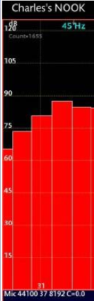
Charlie,I used the MCM 55-2421 8" woofer. The woofer is 87db and the Holliman cab seems to be that efficient.
I simply took the 10" plans and reduced the dimensions by 20% to come up with an 8" version.
In Room RTA with Pink Noise:
The scale on the RTA is 0 to 16k HZ.
Thanks for posting what appears to be the first actual measurement in the entire thread.
A 1/3 octave RTA does not normally have filters below 20 Hz, the screen shot below shows what appears to be the 20, 25, 31, 40, and 50 Hz bands.
Your response curve shows approximately 88 dB at 40 Hz, 65 dB at 20 Hz.
That is a 23 dB drop, considering how "jumpy" RTA readings are, reads pretty much like a classic 24 dB per octave drop below Fb.
A sealed box normally rolls off at only 12 dB per octave, if you would like more extended LF you might consider sealing the box.
Does not appear to have response remotely "infrasonic", but decent LF for an 8".
Art
Attachments
good to hear - if that 31Hz band was steady then pretty nice - got any pictures of the cabinet? - Art - are you suggesting a back chamber ?
No, I'm suggesting that Charlie's RTA picture shows that his cabinet rolls off at twice the rate of a sealed box, and if he is after more "Infra Bass", sealing the box would achieve that.good to hear - if that 31Hz band was steady then pretty nice - got any pictures of the cabinet? - Art - are you suggesting a back chamber ?
Of course, the sealed box extended LF would barely be audible at 20 Hz before hitting the speakers excursion limits 🙄.
Does not appear to have response remotely "infrasonic", but decent LF for an 8".
Art
Actually that particular 8 inch driver models particularly well in flh and tapped horn designs with tuning as low as 20 hz with meaningful output.
In simulations I noticed that the mcm 55-2421 is basically a drop in replacement for the tang band w6-1139 (other than the size difference). Here's an actual measurement of the first tapped horn I ever made back in 2009 using the 1139. Measurement was taken outside in my driveway. (The tapped horn is well stuffed in this pic. It's not a great design but not bad for a first try.)
An externally hosted image should be here but it was not working when we last tested it.
Simulations suggest I could swap the mcm driver in with no audible difference. Simulations also suggest that this design can do about 105 db in 2 pi space (at the lowest point in the curve) with either driver.
So IMO there are better uses for this driver and better alignments if low tuning is desired.
G. Holliman enclosure, post #173
Hi there J: You deserve credit for shepherding two threads on the G. Holliman enclosure. I was planning to read through this thread again, thanks for the prompt. Especially, liked your closing sentence: "But as far as I can tell, this is the most space efficient, cost effective way to get a 7hz F3." You certainly inspired many others to keep up interest and to see another completed (and posted tests) is encouraging (good low Hz response from an eight inch driver too) . ...regards, Michael
Bjorno, I have to give you credit. I didn't think this design could be modelled with existing software, but I think you are creating an accurate picture of what we are hearing. But I do not agree that noise is inherent in the design.
You didn't expect the 10 inch version to get down to 5 hz, did you? The patent makes no mention at all of 5 hz. It mentions the 15 inch version got to 7 hz with little loss of volume. It is the doc with the plans that mentions 5 - 25 hz and that is the catchphrase I have been referring to so often. How much can you expect from a 10 inch driver? I was expecting a bit lower than 22 hz (referring to attachment 3), maybe 15 hz or so, but certainly not 5 hz from the 10 inch box.
Also referring to attachment 3, the tuning range is obviously from about 22 hz and up, which, on the second graph looks like a phase lock, as I understand it, as the blue and red line overlap. That means that the phase matches over it's entire usable range, even if the range isn't as much as expected. Actually your current work seems to prove that this design works, although the 10 inch version may be tuned a bit high.
So the 10 inch version isn't an infrasonic powerhouse. This is not really big news to me, although I think a 15 hz f3 is possible with the correct driver and using the plans. And with small mods, such as in attachment 4, a single 10 inch driver is putting out levels of over 95 db down to 10 hz with only 16 watts. What other design can claim those numbers?
I never realistically expected any more than a 7 hz f3 from the 15 inch version following the plans. According to TwisterZ's predictions, that might even be a stretch. But as far as I can tell, this is the most space efficient, cost effective way to get a 7 hz f3.
Hi there J: You deserve credit for shepherding two threads on the G. Holliman enclosure. I was planning to read through this thread again, thanks for the prompt. Especially, liked your closing sentence: "But as far as I can tell, this is the most space efficient, cost effective way to get a 7hz F3." You certainly inspired many others to keep up interest and to see another completed (and posted tests) is encouraging (good low Hz response from an eight inch driver too) . ...regards, Michael
Please understand that the only reason I continue to post in these threads is in retribution for my extreme naivety back in 2006 when I championed this design. I didn't even know what Akabak was, had never even tried Hornresp at that time. I thought there was some type of magic going on with this unconventional loading method. That's easy to do when you don't understand the math and physics but I've since learned that there is no magic to be found anywhere in audio.
If I could I would go back and delete all my old posts on this subject, in fact I'd delete these entire threads. It's not that these designs don't work, they do. The problem is that the people that get excited about them can't simulate them. The people that can simulate them don't build them.
It should be noted that bjorno did not simulate the exact design from the plans, he simulated a test box of his own design that has some important differences.
Since my interest has been somewhat renewed to see exactly what this design can do I think I'm going to simulate it myself with Akabak exactly as outlined in the plans in the next few weeks as time permits. (I'm going to be very busy for at least the next few days but if I can find the time I'll do it asap.)
I'm going to need to find the plans to get the exact dimensions first so if someone could give me a direct link or email them to me I'd appreciate it.
From what I remember the driver fires into a very small hole and that's the first problem I'm expecting to see when using a modern driver. Tremendous velocity right at the "throat" is going to cause all kinds of noise problems.
EDIT - I found the plans. It's a dimensionless drawing so I'm going to have to use the panel dimensions to figure out the box dimensions. I guess this is going to take awhile.
Last edited:
G. Holliman encl.
Hi there J: As you pointed out in post #344, herein, the path to low bass response is through larger enclosures...I hope you are using the "original G.H." the larger one.
Within the thread, others posted that the space above the driver was enclosed (dotted lines in one sketch). QUESTION: Is the driver a sealed enclosure on one side and is there some dampening material in the closed space? Also, the small hole that the signal passes through will present a large compression ratio to the driver. ...regards...Michael
Please understand that the only reason I continue to post in these threads is in retribution for my extreme naivety back in 2006 when I championed this design. I didn't even know what Akabak was, had never even tried Hornresp at that time. I thought there was some type of magic going on with this unconventional loading method. That's easy to do when you don't understand the math and physics but I've since learned that there is no magic to be found anywhere in audio.
If I could I would go back and delete all my old posts on this subject, in fact I'd delete these entire threads. It's not that these designs don't work, they do. The problem is that the people that get excited about them can't simulate them. The people that can simulate them don't build them.
It should be noted that bjorno did not simulate the exact design from the plans, he simulated a test box of his own design that has some important differences.
Since my interest has been somewhat renewed to see exactly what this design can do I think I'm going to simulate it myself with Akabak exactly as outlined in the plans in the next few weeks as time permits. (I'm going to be very busy for at least the next few days but if I can find the time I'll do it asap.)
I'm going to need to find the plans to get the exact dimensions first so if someone could give me a direct link or email them to me I'd appreciate it.
From what I remember the driver fires into a very small hole and that's the first problem I'm expecting to see when using a modern driver. Tremendous velocity right at the "throat" is going to cause all kinds of noise problems.
EDIT - I found the plans. It's a dimensionless drawing so I'm going to have to use the panel dimensions to figure out the box dimensions. I guess this is going to take awhile.
Hi there J: As you pointed out in post #344, herein, the path to low bass response is through larger enclosures...I hope you are using the "original G.H." the larger one.
Within the thread, others posted that the space above the driver was enclosed (dotted lines in one sketch). QUESTION: Is the driver a sealed enclosure on one side and is there some dampening material in the closed space? Also, the small hole that the signal passes through will present a large compression ratio to the driver. ...regards...Michael
I'm using these plans https://www.google.ca/url?sa=t&rct=...=876L2Fexvywy4vsrnx6lXw&bvm=bv.49641647,d.aWM and simulating the largest size.
In these plans is an Appendix A - Builder's Experience by Ryan Reynolds and there's a great picture of the enclosure without the driver attached. That should make things more clear for you. As for stuffing, I'm not sure. I'll have to read the plans to find out if any is recommended anywhere but I don't think so.
Ok, I'm early in the process and I'm already having trouble. The dimensions of circle B and circle C are listed as 3 and 6 inches respectively. Here's a picture of them (red added by me.)
This drawing is generally not to scale but in the top sketch circle C's diameter is clearly not 2x the diameter of circle B. I measured it to be sure.
In the bottom sketch I need to know if the diameter of circle C is 6 inches at the top of the board or at the bottom of the board (the bottom being the larger part of the hole due to the chamfer).
This dimension is important because it affects not only the size of the duct into the chamber but also the cross sectional area of the beginning of the port (S1 in Hornresp speak).
I suppose I could model it both ways but I'd prefer not to if there's a clear answer that I'm not seeing. I read the entire text in this document and I'm still unclear.
Help would be appreciated, I can't proceed without this dimension unless I'm forced to simulate it both ways.
An externally hosted image should be here but it was not working when we last tested it.
This drawing is generally not to scale but in the top sketch circle C's diameter is clearly not 2x the diameter of circle B. I measured it to be sure.
In the bottom sketch I need to know if the diameter of circle C is 6 inches at the top of the board or at the bottom of the board (the bottom being the larger part of the hole due to the chamfer).
This dimension is important because it affects not only the size of the duct into the chamber but also the cross sectional area of the beginning of the port (S1 in Hornresp speak).
I suppose I could model it both ways but I'd prefer not to if there's a clear answer that I'm not seeing. I read the entire text in this document and I'm still unclear.
Help would be appreciated, I can't proceed without this dimension unless I'm forced to simulate it both ways.
why not crunch a range of sizes and see if a trend shows up it might help to fine tune the design a little. Thanks for doing this. Best regards Moray James.
why not crunch a range of sizes and see if a trend shows up it might help to fine tune the design a little. Thanks for doing this. Best regards Moray James.
That would be nice but ...
I'm about three hours into this and I'm still trying to figure out the dimensions of this thing. It isn't easy since all I've got to work with is a few sketches and a cut sheet list with panel dimensions. And if you look at the plans the panel dimensions (even the ones with angles and chamfers) are only listed with a single dimension.
This is the kind of crap I'm dealing with.
An externally hosted image should be here but it was not working when we last tested it.
This makes the process very difficult. If I just wanted to build it, it would be quite simple, the cut sheet has all the info I need (with the exception of the exact details of hole C). But reverse engineering it with these sketches and the cut sheet panel dimensions is a whole other thing.
I'm going to post up a lot of info when I get done. I'm going to show all my work including how I came up with the dimensions I used to simulate so everyone can check my work and make sure I didn't make any mistakes. I'll also post up the Akabak script with notes on what is what and what to change if you want to make changes. I'm even going to show how to start it in Hornresp (let Hornresp do the heavy lifting) and then import the Hornresp data into Akab
Last edited:
That's a worthy scientific attitude.why not crunch a range of sizes and see if a trend shows up it might help to fine tune the design a little. Thanks for doing this. Best regards Moray James.
I wonder if the same parameterization could be accomplished by stuffing blocks of solid-stuff into the resonant chamber* and similar adjustments to a single unit?
Ben
*folks (including me) have experimented with the sealed back chamber of the Klipschorn that way for years using bricks (it is a small volume).
Last edited:
Now I'd like to raise a deeper question, one touching on listening AKA psycho-acoustics.
My impression is that wise persons (and that sometimes includes modelers) have concluded we are "blowing into a coke bottle" or tickling a Helmholtz resonator* or otherwise creating a frequency response composed of one or a few resonances. If freddi will excuse me, some have conceived the Karlson that same way.
So my question is, "Is that a fair way to make sound or not? Does it matter if a certain band is "artificially" enhanced at spots that way rather than continuously across the band and smoothly? Why complain if some builders are vastly delighted thinking they have infra-sonic sound when in fact they just have a giant bubble at 7 Hz?"
Or is it simply an empirical question: if it tests well with listeners who can't tell one type of enclosure from another, it is good.
(Although I am hesitant about other resonance and phase-game enclosure designs, I'll try to avoid making enemies by not naming certain other popular enclosure designs here.)
Ben
*early posts (and the inventor) have talked about the goosing whatever the infra-sonic output this design achieves through architectural acoustics including room modes and that hot topic, "room gain." I feel that's philosophically slightly different than the resonances I'm talking about in this post.
Last edited:
Ben you could make the exact same argument at the opposite end of the spectrum with a one inch tweeter which is only capable of making 18 or 20 KHz by means of an "oil can" resonance on the centre 1/8 inch of the dome. It is a one note wonder like a doorbell which gets rung when you need a little high end to remind folks that it exists.
So the size of the bass bubble will determine how useful it is. Reflex vents only work over an range of 5 - 6Hz but that can be very useful. If you get there and it works do you really care how you got there? You are after all pulling a rabbit out of a hat.People want big loud deep sound out of their shoe box size speakers. I hear what you are saying but what are the alternatives? Do you think people will accept the stacks of subs necessary to do this the way the pros do? Best regards Moray James.
So the size of the bass bubble will determine how useful it is. Reflex vents only work over an range of 5 - 6Hz but that can be very useful. If you get there and it works do you really care how you got there? You are after all pulling a rabbit out of a hat.People want big loud deep sound out of their shoe box size speakers. I hear what you are saying but what are the alternatives? Do you think people will accept the stacks of subs necessary to do this the way the pros do? Best regards Moray James.
Hello Zobsky,
I used the MCM 55-2421 8" woofer. The woofer is 87db and the Holliman cab seems to be that efficient.
I simply took the 10" plans and reduced the dimensions by 20% to come up with an 8" version.
In Room RTA with Pink Noise:
An externally hosted image should be here but it was not working when we last tested it.
The scale on the RTA is 0 to 16k HZ.
Charlie
Cool, I have one of those lying around.
So my question is, "Is that a fair way to make sound or not? Does it matter if a certain band is "artificially" enhanced at spots that way rather than continuously across the band and smoothly? Why complain if some builders are vastly delighted thinking they have infra-sonic sound when in fact they just have a giant bubble at 7 Hz?"
Hey Ben, thanks for raising that deep question for the 6000th time.
You have a horn, don't you? Klipsch horn or something? Where do you think the high spl comes from? Check the impedance curve.
If you don't want any resonances you are stuck with OB or heavily stuffed sealed boxes. And you can only listen to them outside.
Is that fair?
You tell me how much driver displacement and amp power it takes to get audible output at 7 hz in 2 pi space (outside) with OB or heavily stuffed sealed boxes. Once you calculate that, get back to me and let me know if it's fair.
- Home
- Loudspeakers
- Subwoofers
- Graham Holliman Velocity Coupled Infra Bass Speaker?