Ok, I'm early in the process and I'm already having trouble. The dimensions of circle B and circle C are listed as 3 and 6 inches respectively.
It's been awhile since I looked at this design, but from memory, the throat is supposed to have the shortest vent length practical, i.e. knife edged to get its acoustic path-length down to its radius*0.613 same as DSL does with its Synergy horn tapped mids, so the 3" - 6" dia. [4x area] difference to create a very shallow, fast expanding baffle thickness 'horn' seems reasonable.
The plan shows the flare on the compression chamber side, so would be hidden from view.
GM
That's the question I'm asking. What's the answer?snip If you get there and it works do you really care how you got there? You are after all pulling a rabbit out of a hat.snip
I am not sure about the appropriateness of your tweeter example. The signal is passed in a band only a portion of the size of the bubble. But for bass, the whole bubble is in the passband.
I have no solid idea what infra-sound sounds like (duh) and so I don't know if a resonance on, say, 7 Hz would represent a discernible coloration.
But in the ordinary range of BR enclosures, my sense if that the tuning presents a coloration unless it is the rare unit which - after endless sophisticated fine-tuning like Toole used to do for Harmon - emerges neutral.
"Coloration" is a parameter, not a golden-eared fantasy. It can be seen in tests or at least inferred from test results. But it does not show up in models, as far as I modestly know. It is obvious that rooms have coloration. So too for many enclosures.
I'm kind of a fan of Karlsons (and freddi) and love the way they make cello sounds so well. Perhaps it is the right collection of resonances that makes things work (albeit only for cellos).
I am surprised by the surly defensive post by just a guy to my question (intended to be as straight-forward as I could make it) and have no reply.
Ben
Last edited:
It's been awhile since I looked at this design, but from memory, the throat is supposed to have the shortest vent length practical, i.e. knife edged to get its acoustic path-length down to its radius*0.613 same as DSL does with its Synergy horn tapped mids, so the 3" - 6" dia. [4x area] difference to create a very shallow, fast expanding baffle thickness 'horn' seems reasonable.
The plan shows the flare on the compression chamber side, so would be hidden from view.
GM
Thanks, but the throat is circle B and I'm asking about circle C which is the entrance to the chamber.
The chamfer is indeed on the inside side of the chamber but it's unclear if the 6 inch diameter is the top or bottom of the chamfer. The diagram I posted is not to scale but seems to suggest the top of the hole (the smaller end) is 6 inches, but the picture I showed in post 355 suggests that chamfered parts should be measured across the longest distance (the larger side of the hole).
I'll just simulate it both ways, with a large and a small hole. The large one will be 6 inches on top and 8 inches on the bottom of the panel, the small hole version will be 4 inches on the top and 6 inches on the bottom.
Last edited:
I am surprised by the surly defensive post by just a guy to my question (intended to be as straight-forward as I could make it) and have no reply.
Ben
You've asked this question several times now (dozens?). IIRC I've answered it at least three times already in different ways in different threads. But you keep asking. IIRC the last time it came up I asked if you have ever heard a tapped horn and I believe you said no. So I don't understand you vendetta against them. (And against other resonant alignments.)
If you want to seriously discuss this try starting a thread on this topic of resonances and your opinion of them instead of bringing it up repeatedly in discussions where resonance is an integral and desired part of the design being discussed. Be prepared to show measurements and/or simulations of the dangers of "trafficking in resonances", not just subjective opinion that it shouldn't be done. Otherwise I'll probably keep answering the same question with the same answer as our paths cross again.
Thanks, but the throat is circle B and I'm asking about circle C which is the entrance to the chamber.
Correct, 'c' is the end of the conical taper according to the drawing, so it begins at the 3" dia. hole on the topside and ends at the 6" dia. termination [c] on the inside, it's just not drawn to scale.
GM
That's the question I'm asking. What's the answer?
I am not sure about the appropriateness of your tweeter example. The signal is passed in a band only a portion of the size of the bubble. But for bass, the whole bubble is in the passband.
I have no solid idea what infra-sound sounds like (duh) and so I don't know if a resonance on, say, 7 Hz would represent a discernible coloration.
But in the ordinary range of BR enclosures, my sense if that the tuning presents a coloration unless it is the rare unit which - after endless sophisticated fine-tuning like Toole used to do for Harmon - emerges neutral.
"Coloration" is a parameter, not a golden-eared fantasy. It can be seen in tests or at least inferred from test results. But it does not show up in models, as far as I modestly know. It is obvious that rooms have coloration. So too for many enclosures.
I'm kind of a fan of Karlsons (and freddi) and love the way they make cello sounds so well. Perhaps it is the right collection of resonances that makes things work (albeit only for cellos).
I am surprised by the surly defensive post by just a guy to my question (intended to be as straight-forward as I could make it) and have no reply.
Ben
I suppose that we would not have much deep bass reproduction at all if it were not for resonant bass reproduction. Truth is that even the bass that we have is not true to life even at 50 Hz most speakers are what 15 to 20 db below a reference level of 1000Hz. Attempting to reproduce true to life bass in our home is often and impossible task in acoustically small rooms which are not physically large enough to propagate such low frequencies in the first place. Our stereos are after all just systems meant to reproduce a real acoustical event can we in all honesty expect them to do that? I think that if you can get things right then you can get close enough to allow us to fool ourselves or to believe the reproduction is real. In the same way you can watch Rich Little in a movie and believe you are really watching Johnny Carson. You know it is not Johnny but you choose to believe that it is. He has the right gestures the right body language, close enough to believe the story. I wish I had a better answer. When you have nothing something even if it is not very good is better than nothing, sort of. It's not but it can seem that way. Thank god that our brains can do so much fudging for us and can make out stereo systems sound do real at times.
I like Karlson's too they can do some interesting things. Best regards Moray James.
Correct, 'c' is the end of the conical taper according to the drawing, so it begins at the 3" dia. hole on the topside and ends at the 6" dia. termination [c] on the inside, it's just not drawn to scale.
GM
An externally hosted image should be here but it was not working when we last tested it.
The details of hole b are clear, it's 3 inches diameter. Hole b is on a whole different panel than hole c. Both sides of hole c are on panel c.
No dimensions of hole c (on either side of panel c) can be 3 inches. Since it's a 45 degree chamfer through 1 inch thick material the larger circle on panel c has to be exactly 2 inches larger in diameter than the smaller circle on panel c. So the hole on one side of panel c is 6 inches, that much is clear but it's not clear whether that's the hole on the top side or the bottom side of panel c (green or purple). The other hole has to be either 4 or 8 inches depending on which side (top or bottom) is the 6 inch hole.
Hope this is more clear.
Last edited:
The Hole in Panel C is cut out to 6" inches for the 15" version and then routed with a 45 degree bit. No dimension is given for the width of the chamfered end of the hole.
Charlie
Charlie
The Hole in Panel C is cut out to 6" inches for the 15" version and then routed with a 45 degree bit. No dimension is given for the width of the chamfered end of the hole.
Charlie
This was my best guess too. The diameter of the chamfered end has to be 8 inches in this case.
If no one objects, this is how I'm going to do it.
Thanks.
The details of hole b are clear, it's 3 inches diameter. Hole b is on a whole different panel than hole c. Both sides of hole c are on panel c.
OK, this is a bit different than what you wrote/implied earlier, though it doesn't change what I said as I was only referring to the hole in the chamber pot.
Regardless, for some reason I thought you trying to work it out from theoretical ideal, but in looking at the whole doc this drawing is from, it spells out that for this particular build that the hole is 6" topside with a 45 deg chamfer [flare out] on the inside, i.e. unless otherwise stated, a panel view is always 'sunny side' up and since the flare out is dashed it's on the bottom side.
GM
The diameter of the chamfered end has to be 8 inches in this case.
Yup.
GM
OK, this is a bit different than what you wrote/implied earlier ...
GM
Perhaps I wasn't clear or maybe it was a misunderstanding. Either way I'm glad the correct dimensions have been established now.
First, let me start by saying I expect people to check my work and make sure there are no mistakes. Please check to make sure I got cross sectional areas right (S1, S2, etc) and segment lengths correct (L12, L23, etc). Check my Hornresp inputs and my Akabak script. I'm going to look it over tomorrow to see if I can spot any errors but I think I captured the essence of this thing pretty well.
Ok, here we go...
First up is a picture showing how I split it up into segments and calculated the compression chamber volume for Hornresp inputs.
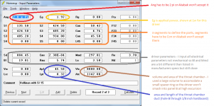
Next we have a picture of my Hornresp inputs. Everything is here except the details of hole c and the compression chamber. When you have to use Akabak I recommend starting with Hornresp first and importing that data into Akabak to continue, unless you are a masochist.
Starting with Hornresp gives a couple of important benefits, it generates the Akabak script for you and it allows you to view a schematic to make sure you aren't making stupid mistakes. Here's a picture of the Hornresp schematic (remember, this doesn't include hole C or the compression chamber but everything else is there).
You can see I chose to use the Stereo Integrity HT 15 inch subwoofer Stereo Integrity | HT Subwoofers since it's a fair value, has 22.5 mm xmax and 600 wrms power rating so it should do what we need it to.
Next I exported the Hornresp data, which is as simple as going to the Input screen, selecting File - Export - Akabak script and then I placed that file into the Akabak script folder.
Then I opened the file in Akabak and continued the script by adding the details of hole C and the compression chamber. Hole C is a waveguide consisting of S5, S6 and L56. The compression chamber is an enclosure with a volume of 200.4 liters and a length of 1m.
(I will put the Akabak script in the next post.)
Then I ran a few simulations starting with frequency response at 1w.
Not quite 7 hz. And clearly either the driver or the box dimensions need to change for smooth response down near tuning but that's not too important right now. Let's continue.
Here's the impedance.
Response at 600 watts.
And driver excursion at 600 watts.
And at this point I was just itching to see the throat velocity (through the 3 inch diameter hole B). Here it is.
Yup, that's approaching 60 m/s inside the passband. In fact this is unacceptable all the way through the passband with the exception of a small area right near tuning.
Unless I've made a terrible mistake somewhere this is not a viable design for modern drivers. Probably not for antique drivers either. Throat velocity like that is going to squeal like a little piggy even with both ends of hole B smoothed (as per the plans).
It's interesting to note that opening hole B up to a 5 inch diameter reduces throat velocity to about 20 m/s and doesn't change the response at all - it really doesn't change anything. But the point is that if it's built according to the plans you are going to see very high velocity through hole B. If I was going to build it I'd make hole B with a 6 inch diameter - that's the same size as hole C and it's as big as you can go without changing the design significantly.
But here's the interesting part. This next picture is the same driver in a similar sized ported box with the same 600w applied.
Easier to build and much MUCH easier to simulate. IMO a much better solution overall.
Did I really just waste 8 hours on this? Yeah, I guess I did.
Ok, here we go...
First up is a picture showing how I split it up into segments and calculated the compression chamber volume for Hornresp inputs.
An externally hosted image should be here but it was not working when we last tested it.
Next we have a picture of my Hornresp inputs. Everything is here except the details of hole c and the compression chamber. When you have to use Akabak I recommend starting with Hornresp first and importing that data into Akabak to continue, unless you are a masochist.
An externally hosted image should be here but it was not working when we last tested it.
Starting with Hornresp gives a couple of important benefits, it generates the Akabak script for you and it allows you to view a schematic to make sure you aren't making stupid mistakes. Here's a picture of the Hornresp schematic (remember, this doesn't include hole C or the compression chamber but everything else is there).
An externally hosted image should be here but it was not working when we last tested it.
You can see I chose to use the Stereo Integrity HT 15 inch subwoofer Stereo Integrity | HT Subwoofers since it's a fair value, has 22.5 mm xmax and 600 wrms power rating so it should do what we need it to.
Next I exported the Hornresp data, which is as simple as going to the Input screen, selecting File - Export - Akabak script and then I placed that file into the Akabak script folder.
Then I opened the file in Akabak and continued the script by adding the details of hole C and the compression chamber. Hole C is a waveguide consisting of S5, S6 and L56. The compression chamber is an enclosure with a volume of 200.4 liters and a length of 1m.
(I will put the Akabak script in the next post.)
Then I ran a few simulations starting with frequency response at 1w.
An externally hosted image should be here but it was not working when we last tested it.
Not quite 7 hz. And clearly either the driver or the box dimensions need to change for smooth response down near tuning but that's not too important right now. Let's continue.
Here's the impedance.
An externally hosted image should be here but it was not working when we last tested it.
Response at 600 watts.
An externally hosted image should be here but it was not working when we last tested it.
And driver excursion at 600 watts.
An externally hosted image should be here but it was not working when we last tested it.
And at this point I was just itching to see the throat velocity (through the 3 inch diameter hole B). Here it is.
An externally hosted image should be here but it was not working when we last tested it.
Yup, that's approaching 60 m/s inside the passband. In fact this is unacceptable all the way through the passband with the exception of a small area right near tuning.
Unless I've made a terrible mistake somewhere this is not a viable design for modern drivers. Probably not for antique drivers either. Throat velocity like that is going to squeal like a little piggy even with both ends of hole B smoothed (as per the plans).
It's interesting to note that opening hole B up to a 5 inch diameter reduces throat velocity to about 20 m/s and doesn't change the response at all - it really doesn't change anything. But the point is that if it's built according to the plans you are going to see very high velocity through hole B. If I was going to build it I'd make hole B with a 6 inch diameter - that's the same size as hole C and it's as big as you can go without changing the design significantly.
But here's the interesting part. This next picture is the same driver in a similar sized ported box with the same 600w applied.
An externally hosted image should be here but it was not working when we last tested it.
Easier to build and much MUCH easier to simulate. IMO a much better solution overall.
Did I really just waste 8 hours on this? Yeah, I guess I did.
|DATA EXPORTED FROM HORNRESP - RESONANCES NOT MASKED
|COMMENT: Holliman with SI 15
|~~~~~~~~~~~~~~~~~~~~~~~~~~~~~~~~~~~~~~~~~~~~~~~~~~
|REQUIRED AKABAK SETTINGS:
|File > Preferences > Physical system constants:
|Sound velocity c = 344m/s
|Medium density rho = 1.205kg/m3
|Sum > Acoustic power:
|Frequency range = 10Hz to 20kHz
|Points = 533
|Input voltage = 1.92V rms
|Integration = 2Pi-sr
|Integration steps = 1 degree ... 1 degree
|Integration method = Cross
|~~~~~~~~~~~~~~~~~~~~~~~~~~~~~~~~~~~~~~~~~~~~~~~~~~
Def_Const |Hornresp Input Parameter Values
{
|Length, area and volume values converted to metres, square metres and cubic metres:
S1 = 135.50e-4; |Horn segment 1 throat area (sq m)
S2 = 424.50e-4; |Horn segment 1 mouth area and horn segment 2 throat area (sq m)
S3 = 485.20e-4; |Horn segment 2 mouth area and horn segment 3 throat area (sq m)
S4 = 934.00e-4; |Horn segment 3 mouth area (sq m)
S5 = 182.32e-4; |Compression chamber waveguide hole 6 inch
S6 = 324.13e-4; |Compression chamber waveguide hole chamfered end 8 inch
L12 = 58.42e-2; |Horn segment 1 axial length (m)
L23 = 4.76e-2; |Horn segment 2 axial length (m)
L34 = 45.50e-2; |Horn segment 3 axial length (m)
L56 = 1e-2; |Compression chamber entry/exit
Ap1 = 45.00e-4; |Throat adaptor entry cross-sectional area (sq m)
Lpt = 0.32e-2; |Throat adaptor length (m)
Vtc = 8000.00e-6; |Throat chamber volume (cubic m)
Atc = 1142.00e-4; |Throat chamber cross-sectional area (sq m)
|Parameter Conversions:
Sd = 804.45e-4; |Diaphragm area (sq m)
Ltc = Vtc / Atc;
}
|~~~~~~~~~~~~~~~~~~~~~~~~~~~~~~~~~~~~~~~~~~~~~~~~~~
|Network node numbers for this back-loaded horn system:
| 0-Voltage-1
| |
|Radiator(1)-5-Driver-6-Chamber-7-Adaptor-8-Segment-9-Segment-10-Segment-11-Radiator(2)
| 8-Segment-12-Chamber
|~~~~~~~~~~~~~~~~~~~~~~~~~~~~~~~~~~~~~~~~~~~~~~~~~~~~~~~~~~
Def_Driver 'Driver'
Sd=804.45cm2
Bl=19.01Tm
Cms=2.38E-04m/N
Rms=5.74Ns/m
fs=18.50Hz |Mmd = 297.81g not recognised by AkAbak, fs calculated and used instead
Le=3.50mH
Re=3.70ohm
ExpoLe=1
System 'System'
Driver Def='Driver''Driver'
Node=1=0=5=6
Radiator 'Diaphragm'
Node=5
SD={Sd}
Label=1
Duct 'Throat chamber'
Node=6=7
SD={Atc}
Len={Ltc}
Visc=0
Waveguide 'Throat adaptor'
Node=7=8
STh={Ap1}
SMo={S1}
Len={Lpt}
Conical
Waveguide 'Horn segment 1'
Node=8=9
STh={S1}
SMo={S2}
Len={L12}
Conical
Waveguide 'Horn segment 2'
Node=9=10
STh={S2}
SMo={S3}
Len={L23}
Conical
Waveguide 'Horn segment 3'
Node=10=11
STh={S3}
SMo={S4}
Len={L34}
Conical
Radiator 'Horn mouth'
Node=11
SD={S4}
Label=2
Waveguide 'Hole C'
Node=8=12
STh={S5}
SMo={S6}
Len={L56}
Conical
Enclosure 'Compression chamber'
Node=12
Vb=200.4L
Lb=1m
Last edited:
it is "Velocity-Coupled" 😀 ...... what about a transflex with narrowing cross-section vs a plain reflex? (down to ~20)
First, let me start by saying I expect people to check my work and make sure there are no mistakes.
Hi just a guy,
Note 3 on the attached screenprint indicates that "segments have to be Con or AkAbak won't accept them".
AkAbak accepts conical, exponential and hyperbolic-exponential horn segments - see example scripts below.
CONICAL:
Waveguide 'Horn segment 1'
Node=8=9
STh={S1}
SMo={S2}
Len={L12}
Conical
EXPONENTIAL:
Waveguide 'Horn segment 1'
Node=8=9
STh={S1}
SMo={S2}
Len={L12}
HYPERBOLIC-EXPONENTIAL:
Waveguide 'Horn segment 1'
Node=8=9
STh={S1}
SMo={S2}
Len={L12}
T={T}
Kind regards,
David
Attachments
I appreciate your in-depth thoughts. But the question remains "what" system does best at the illusion of Carnegie Hall or the "down the hall" test?I suppose that we would not have much deep bass reproduction at all if it were not for resonant bass reproduction. Truth is that even the bass that we have is not true to life even at 50 Hz most speakers are what 15 to 20 db below a reference level of 1000Hz. Attempting to reproduce true to life bass in our home is often and impossible task in acoustically small rooms which are not physically large enough to propagate such low frequencies in the first place. Our stereos are after all just systems meant to reproduce a real acoustical event can we in all honesty expect them to do that? I think that if you can get things right then you can get close enough to allow us to fool ourselves or to believe the reproduction is real. In the same way you can watch Rich Little in a movie and believe you are really watching Johnny Carson. You know it is not Johnny but you choose to believe that it is. He has the right gestures the right body language, close enough to believe the story. I wish I had a better answer. When you have nothing something even if it is not very good is better than nothing, sort of. It's not but it can seem that way. Thank god that our brains can do so much fudging for us and can make out stereo systems sound do real at times.
I like Karlson's too they can do some interesting things. Best regards Moray James.
Relating back to the question of the goodness of a "thumper" infra-sonic speaker (not asking for moment if the Holliman produces anything infra-sonic or not), possibly the way to look at it is according to the ability of people to hear differences between notes.
I know it is weird to talk about "hearing" the difference between 7 and 8 Hz. In fact, maybe with infra-sonic sound, the only issue is what is your sternum resonant frequency (somebody posted that long ago, if I recall). But if you can't distinguish between say 4 Hz and 10 Hz, is just doesn't matter if the speaker is thumping out nothing except a Helmholtz resonating 7 Hz. And so, a thumping, resonating infra-sonic speaker will always sound great if it pumps out anything anywhere infra-sonic, esp. when aided by acoustical factors in a tightly sealed room.
The question of quality is quite different in the range of the upper bump on BR enclosure output (strictly speaking, it isn't a resonance but just part of a resonance, kind of). In that frequency range, say around 30-40 Hz, you can discriminate with some precision. So some enclosures seem to have "one-note bass" because you can detect it is the same note all the time.
Ben
Hi just a guy,
Note 3 on the attached screenprint indicates that "segments have to be Con or AkAbak won't accept them".
AkAbak accepts conical, exponential and hyperbolic-exponential horn segments - see example scripts below.
Kind regards,
David
Yes, this is true and thanks for correcting that. What I should have said to be more accurate is that it won't accept PAR, which I would prefer to use if it was available.
it is "Velocity-Coupled" 😀 ......
Yes, yes it is.
what about a transflex with narrowing cross-section vs a plain reflex? (down to ~20)
What about it? Are you asking me to simulate it? It's trivially easy compared to this box but I'm not really that interested, if you want a tapped horn it's easy enough to design one from scratch.
But if you want to simulate it I can help.
You took one for the team 😉.Not quite 7 hz. And clearly either the driver or the box dimensions need to change for smooth response down near tuning but that's not too important right now. Let's continue.
Response at 600 watts.
And driver excursion at 600 watts.
And at this point I was just itching to see the throat velocity (through the 3 inch diameter hole B). Here it is.
Yup, that's approaching 60 m/s inside the passband. In fact this is unacceptable all the way through the passband with the exception of a small area right near tuning.
Unless I've made a terrible mistake somewhere this is not a viable design for modern drivers. Probably not for antique drivers either. Throat velocity like that is going to squeal like a little piggy even with both ends of hole B smoothed (as per the plans).
It's interesting to note that opening hole B up to a 5 inch diameter reduces throat velocity to about 20 m/s and doesn't change the response at all - it really doesn't change anything. But the point is that if it's built according to the plans you are going to see very high velocity through hole B.
Did I really just waste 8 hours on this? Yeah, I guess I did.
"Throat velocity like that is going to squeal like a little piggy" seems to be the operating principle for the low frequency "velocity coupled" whistle effect .
Both your sim and Charlie's RTA show nothing much audible from this design down low, but a LF "whistle" in the right room could be the artifact that has generated interest, and that whistle noise probably is generated just as effectively by a high Fs low Xmax cone as a "modern" low FS high Xmax driver.
Art
- Home
- Loudspeakers
- Subwoofers
- Graham Holliman Velocity Coupled Infra Bass Speaker?