That description has similarity to the many years of
discovery that I have put in to making LDR's sound the best
they can, using also a single gang pot, and low current.
The boards I do, just 5ma with Ron of 115 ohms, and
on signal side audio is dead quiet at no volume.
Forward voltage measuring between 1.69 V and 1.33V with volume range
accordingly far less unnecessary stress on the LED part of the LDR
and sounds much better.
Cheers / Chris
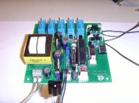
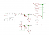
I have tried to operate the LDRs from a dual digital (!) potentiometer, which is followed by a VCCS (see attached images).
But it does not work.
The initial values of the serial resistor (8k5) and shunt resistor (45 Ohm) look good, but when I increment the input to the digital potentiometer by a value of 1 (resulting in an in increase / decrease of about 19mV to the input of the CCS),
the LDR's resistor values resulted in 1k6 for the series- and 46 Ohm for the shunt-LDR - which is an absolute NOGO.
Fenris would you please be so kind and publish your LM134 schematic?
Best regards - Rudi
Attachments
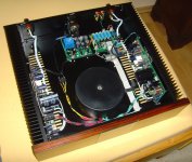
I have just measured the input-impedance (resistance) of my own SYMASYM / LDR attenuation on the right channel, being done by a dual log analog ALPS - potentiometer (see image attached).
The input-impedance (resistance) does never drop below 10k, though it varies from 10 - 11k5 (so there is some room to optimize it via the 1k - potentiometers).
Maybe that I will be able to maintain an input-impedance of about 7k5 for the digital RPRE (shown above) - by the PIC's firmware (! - I will adjust the digital potentiometer to adhere the shunt -
LEDs to shine upon the shunt-LDRs). But this will never be a "general approach". It will be for my "digital prototype" only.
Best regards Rudi_Ratlos
Attachments
- Status
- Not open for further replies.