Hi would this be any good ?
bought with a job lot on ebay .
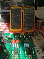
i have removed 1 of the 4 2N5566 dual fets and it was very closely matched .
I am currently building a Mezmerize B1 buffer .
would it be worthwhile building this in to a chassis or just stick with the Mezmerize build .
20190621_145946 by glenn jarrett, on Flickr
20190621_150020 by glenn jarrett, on Flickr
20190619_141649 by glenn jarrett, on Flickr
I have the exact same preamp board which I am using as my main preamp since 2013. Never had any issues with it. It works perfectly fine and I think it sounds quite detailed.
I have never carried out measurements but it's dead silent. It gets a little warm but nothing to worry about.
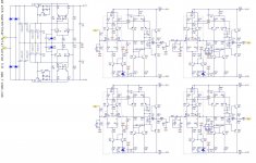
The board layout looks like the original G27 preamp board
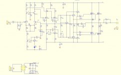
schematic attached
Attachments
I have had that preamp for quite a while. I like it too. However, I split it into two separate parts.
I have already asked the question, but no reply.
Why do you connect two preamps one after another. First you amplify the line level, then you attenuate it, then you amplify it again. Any particular reason?
I have already asked the question, but no reply.
Why do you connect two preamps one after another. First you amplify the line level, then you attenuate it, then you amplify it again. Any particular reason?
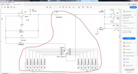
hi.
can anybody provide the values in the telos schematics i marked in the screenshot?
thanky you.
does anybody have any infos on this question?
thank you
regards
Attachments
Last edited:
Pity, I thought these kits would be for power amplifiers, not preamplifiers, which I don't find are necessary anymore.
Pity, I thought these kits would be for power amplifiers, not preamplifiers, which I don't find are necessary anymore.
Well, perhaps start another thread for Goldmund Preamp discussion?
I have been hoping this for a long time, it's time for preamp🙂
i fully agree with that idea. It's time for the matching preamp for the GM8 Deluxe, which is actually running with a Hafler SE-100, fully JFET design.
And i like the sound of that combination.
Günni
And i like the sound of that combination.
Günni
i fully agree with that idea. It's time for the matching preamp for the GM8 Deluxe, which is actually running with a Hafler SE-100, fully JFET design.
And i like the sound of that combination.
Günni
Are you Günther that mailed to me?
Please let me know if you are safe, I have written mail to you.🙂
I have the exact same preamp board which I am using as my main preamp since 2013. Never had any issues with it. It works perfectly fine and I think it sounds quite detailed.
I have never carried out measurements but it's dead silent. It gets a little warm but nothing to worry about.
The board layout looks like the original G27 preamp board
schematic attached
Hi,
It looks like you get the board from China?
Hi,
It looks like you get the board from China?
This is right, though I cannot find this board or the seller on ebay any more
This is right, though I cannot find this board or the seller on ebay any more
Well, I know this guy. He still sells GM27 pre and GM power amp kits.
As I know, he is not good at English and a bit lazy to sell goods internationally, but his kits are still available in the market.
I know this man for several years, we are in the same social media group, though I never meet him as we are not in the same country.
I don't know if we are talking about the same guy, but when I asked for information regarding the adjustment of the pots or a schematic, I got no reply..Thankfully, I was able to find the schematic some years later after a google search.
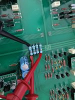
One thing I have done was to change the electrolytic capacitors in the power supply. Since the ac voltage of the transformer is 2x45V the dc voltage that the filter capacitors see is up to 63V which is their rating. Therefore I used 1000uF/100V capacitors. No need to change all of them, but surely those four filtering capacitors just after the rectifier bridge need to change
By the way I suppose that each pot is a dc offset adjustment for each amplification stage and the switch should attenuate the signal coming out of the first stage. Now since the volume pot is sitting between the two stages I guess that each stage acts also as a buffer to match the impedance between a line source and a power amp and the switches will control the total gain of the preamp. Having the volume pot away from the input and/or the output of the circuit should be a good thing since the impedance is kept constant no matter the position of the volume pot which is nothing more than a voltage divider..(of course it depends on how it is wired in the circuit)
Last edited:
carlmart, thanks for the suggestion, changing the capacitors is easy, I can do that from top of the board, and see if I can measure any improvement, but as I explained I use limited setup, just a laptop with RightMark software, no fancy stuff
as for adding the zener and other diode for drivers, that would likely require removing the boards from the heatsink...so I will see about that
Hello hm3s goldmund29 clone scheme?
Goldmund 27 DIY build
Hi,
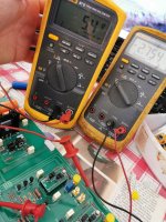
I build up two GM27 preamps using Motorola MPSA42 & MPSA92, the one i build without machting the offset on the output was 60mV - 70mV what is pretty high. So matching the MPSA is needed at least they are used in the Current Mirrors. When i build with the matched MPSA offset was 5mV to 10mV without for touching the offset pots.
Br Walter
Hi,
I build up two GM27 preamps using Motorola MPSA42 & MPSA92, the one i build without machting the offset on the output was 60mV - 70mV what is pretty high. So matching the MPSA is needed at least they are used in the Current Mirrors. When i build with the matched MPSA offset was 5mV to 10mV without for touching the offset pots.
Br Walter
Attachments


Hi,
I build up two GM27 preamps using Motorola MPSA42 & MPSA92, the one i build without machting the offset on the output was 60mV - 70mV what is pretty high. So matching the MPSA is needed at least they are used in the Current Mirrors. When i build with the matched MPSA offset was 5mV to 10mV without for touching the offset pots.
Br Walter
may i ak, where you got the pcb´s from?
I believe this is a schematic of a Telos 390. Look at post #262@ Sensation45 here is the Goldmund 29 diagram you are looking for😕
Hello hm3s goldmund29 clone scheme?
Are you looking for the schematic for the HM3S board?
Attachments

Hello hm3s goldmund29 clone scheme?
you could just google it
Attachments
In case anyone is interested, here is Keantoken’s take on this amp (10 years in the making) but with state of the art layout by JPS64:
Keantoken's Aurum-X 300w Amp with LatFETs
Prototype PCBs are in...
Front End mezzanine:
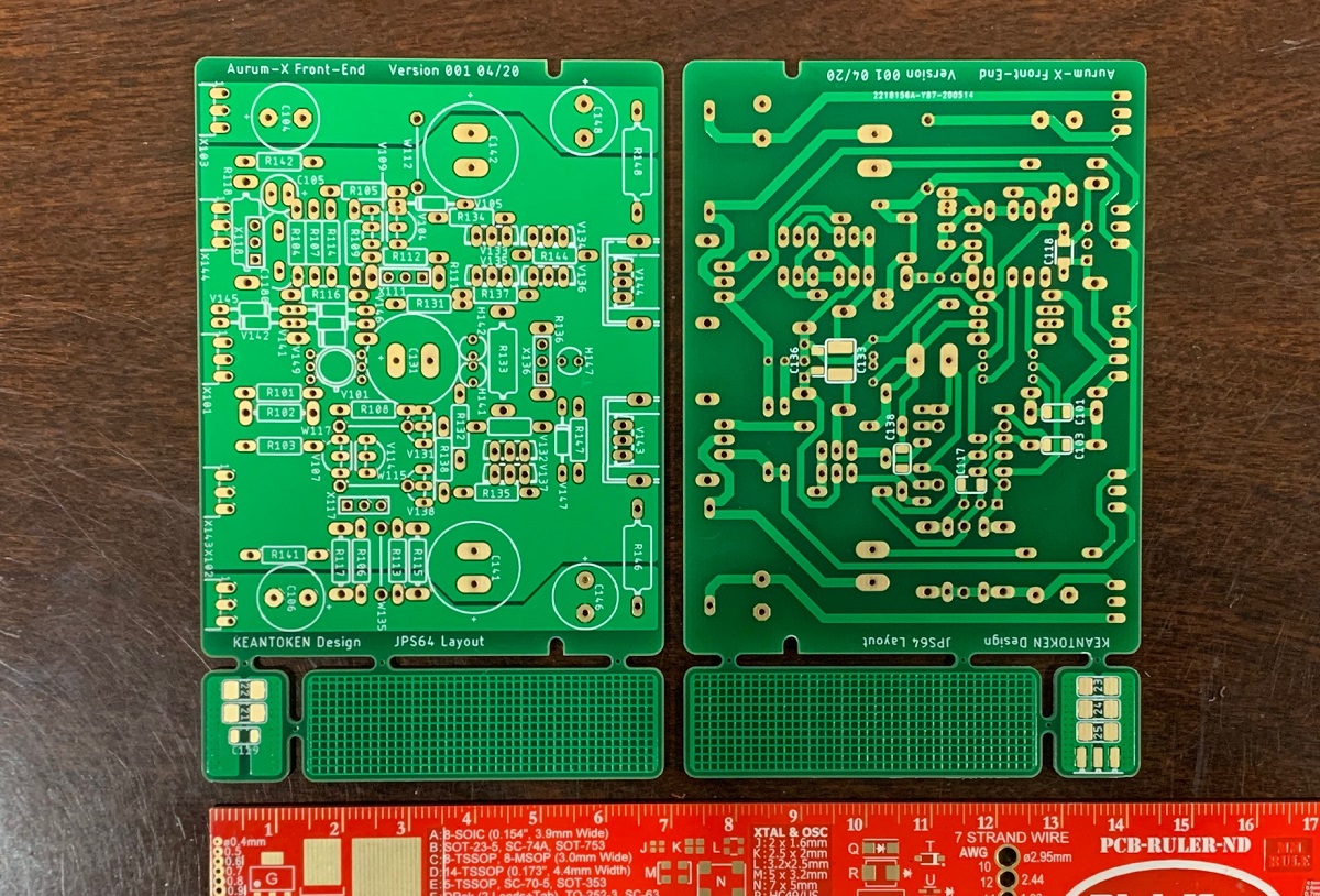
Main amp board:
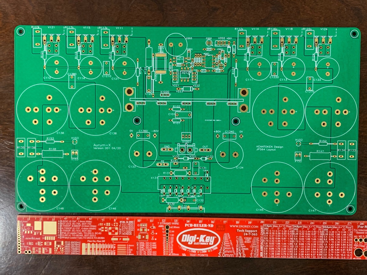
I just need to find time to build it. This will be an epic build with the outlay of resources needed for the 16x 100v rail caps, the 12 latFETs, and dual 600VA toroidal trafos, and miscellaneous parts and pieces. The PCBs are huge 2mm, 2oz, ENIG.
It will be fun once finished though. Hopefully will also sound epic.
Keantoken's Aurum-X 300w Amp with LatFETs
Prototype PCBs are in...
Front End mezzanine:
Main amp board:
I just need to find time to build it. This will be an epic build with the outlay of resources needed for the 16x 100v rail caps, the 12 latFETs, and dual 600VA toroidal trafos, and miscellaneous parts and pieces. The PCBs are huge 2mm, 2oz, ENIG.
It will be fun once finished though. Hopefully will also sound epic.
- Home
- Amplifiers
- Solid State
- Goldmund Wiki and build 2017