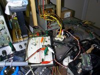
How do you manage to work in such a mess Keat?
My workspace is similar. I find I can instinctively find what Im looking for. The only time things get lost is when I tidy up🙂
If I had a lot of space I could manage instinctively pretty well. However I don't have anywhere to store stuff, let alone organize it, and all my stuff has to be stored on my workbench (desk) until I need it.
- keantoken
- keantoken
Is there a matching jig in there as well?
I assume you mean Hfe matching, and no. I need to find an IC socket or something so I can make a more convenient and accurate rig.
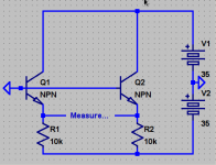
Question. Is it better to match Vbe with B and C shorted, or without? I would think the latter, since it's more like how the transistor will be used in the circuit.
- keantoken
You need to match Vbe at a specific collector current. You should do this at the nominal value of Vce in the actual circuit. This generally means the base and collector should not be shorted.
Well that is really odd. I just tried to build a matching rig on my breadboard and it oscillated at 50MHz, goofing up all my equipment!
That's just wrong...
- keantoken
That's just wrong...
- keantoken
keantoken,
The circuit will absolutely be stable, because the transistors have an infinite fT and 0 capacitances. If you use real transistors it might go unstable, but it is not likely.
Rick
The circuit will absolutely be stable, because the transistors have an infinite fT and 0 capacitances. If you use real transistors it might go unstable, but it is not likely.
Rick
Yes, I BUILT the circuit and it oscillates. When I remove the power leads, everything is fine. I add the power leads again, and it oscillates...
- keantoken
- keantoken
You always have to put good HF bypass caps across the power supplies. These caps need to be close to the transistors. Also keep the leads from the bases to common short to minimize inductance.
This way is simpler and uses less components. It will work just as well... It would be nice to have individually variable +- supplies though, so Vce and Ic can be varied separately.
I just built it this way and it still wants to oscillate, though sporadically... This oscillation occurs whenever the rectifier diodes are forward-biased. So this seems to serve as an indication of my problem...
- keantoken
I just built it this way and it still wants to oscillate, though sporadically... This oscillation occurs whenever the rectifier diodes are forward-biased. So this seems to serve as an indication of my problem...
- keantoken
Attachments
Keantoken: and Others
I have been working on several things, but I decided to let you start in on the actual testing of the amp.
I ran into some self inflicted wounds with bad jumpers and more. And in the process tore up my power supply board I had made for testing. While preparing to make another one, I thought about your admonition that the design I had built did not fit every criteria you wanted to address. I am talking about the post 1421 and 1442. Also should your Cap multiplier be inserted between the pre regulator and the front end of the amp.
So, IF and when you have a few moments will you post a schematic of a pre-regulator that works fairly well, it does not have to be perfect. JUST functional for basic testing purposes.
I have done a transformer board to feed it.
I have also finished my variac supply for the sake of testing, I have got to address some issues with it also, but it works well and is been a GOD send for my purposes. Along with the Keithley 192: 5 or 6 digit meter😀 I have got to find a AC plug in for it.
Other wise carry on...
I am not going out much with Gasoline selling for more than cheap liquor, I do not even drink that much...😛
It is like the cost of those 10 cent steel washer for the bolts at Lowes... shameful.
Attachments
It is like the cost of those 10 cent steel washer for the bolts at Lowes... shameful.
Cheaper (and I've done it) to punch holes through pennies. 1 cent washer.
Krisfr, I meant for there to be only one frontend regulator for the official design. However if you want to use more than one, I recommend putting the shunt design closest to the amp circuitry, and the preregulator can be whatever you choose.
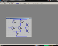
For basic testing no regulator is needed. Attached is the barest shunt regulator version. If this doesn't work, then none of the other versions will work.
- keantoken
For basic testing no regulator is needed. Attached is the barest shunt regulator version. If this doesn't work, then none of the other versions will work.
- keantoken
Attachments
Last edited:
Keantoken:
So in this order, The transformer board in post 1572, a pre-regulator, then shunt from post 1574, then the amp front end.
Any suggestions for the pre- regulator? ANY ONE can suggest it.
Can the pre-reg and the shunt go on the amp board, I am just trying not to put AC on the main amp board.
How is your testing coming?


Cheaper (and I've done it) to punch holes through pennies. 1 cent washer.
Criminal !! 😀 (in the US , but not entirely in canada- vague law ). 😀
OS
You could use the K-multiplier. It is simple and well-performing. How much ripple do you expect from final supply, at say 50mA current? I could adjust the Kmultiplier for a HV supply. It would not need a heatsink.
There is nothing wrong with having all regs on the board. I would suggest local decoupling both at the rectifier and at the input to the board.
I haven't done any testing yet, I'm still working out how I will wire the prototype.
- keantoken
There is nothing wrong with having all regs on the board. I would suggest local decoupling both at the rectifier and at the input to the board.
I haven't done any testing yet, I'm still working out how I will wire the prototype.
- keantoken
Here it is. I think this is final, no one has complained in several pages. Go ahead with it.
I will post the regulator schematic later.
- keantoken
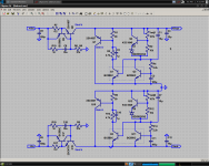
re: schematic of post #783
Don't understand position of C15, across R3 would make more sense?
I mean, we got to drive gates, which need same pull up slew as pull down.
Yet we got emitter vs 220R+emitter difference between up and down drive.
Only mere 100R gate stopper in series doing anything to bring symmetry.
Wouldn't a cap across R3 220R (maybe a bigger cap) drive more equally?
If so, would it make the small C15 in its current position redundant?
- Home
- Amplifiers
- Solid State
- Goldmund Mods, Improvements, Stability