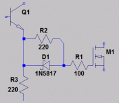
C15 helps enclose the bottom of R21 in the miller feedback loop. This helps keep HF behavior similar in both output halves. Otherwise, the halves of the VAS would be doing different things, possibly wasting energy in the output stage in the form of transverse currents. This matters for pulse behavior, as I seem to recall (Cdom alters the symmetry of VAS currents). The lack of cap across R3 increases isolation between the FETs and lowers risk of spurious oscillation. Also, if the cap were placed across R3 without a cap across R21, it would become another vulnerability for transverse currents. This all improves pulse behavior, which is important if we want this amp to spec at a high slew rate. As for audio, I dunno.
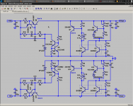
I believe there is a more recent schematic, I think that is an old one.
How is the trebuchet?
- keantoken
I believe there is a more recent schematic, I think that is an old one.
How is the trebuchet?
- keantoken

Seriously Kean, you got mosfet gates misdriven such they turn on at faster speed
than they can be turned off. There ain't gonna be symmetry of push and pull when
the waveform gets moving fast.
Unlike your Allison output stage, there's no local device turned backward to watch
this mismatch of drive slew happen and immediately correct it. Only a cap coupled
global loop watchin' over the sum of two source followers with different delays.
------
I take back about global loop bein' cap coupled. Its still a long fix to a short problem.
And while it may fix sum of mismatched slews, it don't make either problem go away.
Linking the drive emitters also "closes whatever in the loop" would be linked by cap
coupling bases. Diode drops, go figure...
Last edited:
I will note this and include it in my prototype.
Another factor affecting this is the base stoppers. Unless these are chosen to give equal time constants, transverse currents can still occur. And this relies on the capacitances of each FET remaining proportional, which will not happen except at crossover.
- keantoken
Another factor affecting this is the base stoppers. Unless these are chosen to give equal time constants, transverse currents can still occur. And this relies on the capacitances of each FET remaining proportional, which will not happen except at crossover.
- keantoken
Reminds me of blocking distortion in tube amps. Same thing only completely different...
Imagine you take this output and jerk it up and down fast enough that the difference
in drive slew becomes significant. The gates pump up charge that eventually prevents
a clean crossing.
Even a big cap across the 220R will eventually pump up if challenged with a continuous
fast squarewave, and for the same reason. If you like, throw a zenier across this cap
to limit the blocking madness from getting too far out of hand. Normal waveforms are
never going to pump up such charges anyway, I'm just nitpickin.
-----
Oops scratch that, your bias pumps in the ON direction. So the bias merely runs away.
Going back to sleep now.
--------
Unscratchify that. Now the driver bjts begin not to cross cleanly, yep blocking...
Last edited:
Criminal ! (vague law )
Likely, the level of money recycling in Can doesn't justify the death penalty.

(opposed to other known places)
Criminal !! 😀 (in the US , but not entirely in canada- vague law ). 😀
OS
It's beyond me why we still have the 1 cent piece - more nuisance than anything else. Round everything off to 5 cents already.
They cost more than a cent to make and stopped being solid copper a few years back (a zinc alloy now with a copper plating).
Make pretty good 1/4" washers in a pinch though.
It's beyond me why we still have the 1 cent piece - more nuisance than anything else.
+1
(it's a global conspiracy)
The Japanese are smart enough to add the hole at production, for carriage bolts go Chinese.
Last edited:
As we approach the rail, bias on the drain goes away.
Miller capacitance approaches symmetry with gate to source capacitance.
We have 100R charging gate (and an ever increasing miller) toward the rail.
Yet 320R must discharge all coulombs of stored miller going away from rail.
No sim today is going to show you how the miller caps change with bias.
Problems with large signals can happen at lower frequency than you might
expect.
----------------------------------------
Might help, or not????
Attachments
Last edited:
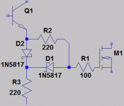
The original Goldmund design didn't have any fancy drive. As much as I would like to explore this option, one of the original design goals was to not get complicated. Many amplifiers exist without fancy drive, so I figure it's not important for audio...?
- keantoken
- keantoken
Will tantalum work for c2 and c10?
You mean for space reasons? Why not a simple Siemens polyester, which is small enough and probably costing less than a tantalum?
You mean for space reasons? Why not a simple Siemens polyester, which is small enough and probably costing less than a tantalum?
Yes that is my goal, the big 1uf I have now are very costly, for a testing project it is ok, but for the future size and cost are to be considered.
It amazes me the cost of things. Vector breadboard (I use to build EVERYthing on it) cost more than black copper clad. the T-42 clips are 4 cents a piece, over 40 dollars a thousand, the way I use to buy them... do not tell me that it is necessary to charge that much for so little metal...
Well let me off the soap box
 , Innovation is being stifled here in the USA. I am willing to bet that breadboard basics are dirt cheap in the far east.
I got about 1000 Wire Wrap Vector pins, bought them never used them, but they do not work for my current mission.
I want companies to make a profit, BUT gouging is not my cup of tea.
It makes NO sense to mount a 4 cent from Mouser transistor on 12 cents worth of clips, and string it to the next one with 10 cents worth of wire.
Well back to making washer out of Lincoln Memorials hehehe😀
58 cents for Dubilier tantalum vs 68 cents for Panasonic SF wouldn't be such a sacrifice.
It sounds as if you will be making thousands of these amps!...
It sounds as if you will be making thousands of these amps!...
What's wrong with regular electrolytic?
John, please forgive my un-educated assumption that the cap needed to be NON polarized...
I am not ever thinking of building thousands of these amps just a few million 😀
Cost are cost and a little saved here and there might give way to some costly and numerous output devices some day, and I might learn a thing or two...or maybe it is some Muntzing going on in my older age...
Besides Keantoken said that THIS design was cheaper and would be more WANTED by all...Hey Keantoken back me up here, how are you coming. I have been torn between car fixing and taxi service for the family and have not my allotted time for sonic machines confabulations and putting togetherness.
C2 and C10 do not need to be nonpolar, and oh BTW, tantalum caps are polarized. Use an inexpensive electrolytic cap with a reasonably low ESR.
John, please forgive my un-educated assumption that the cap needed to be NON polarized...
Bipolar electros are readily available but, like sawreyrw says, these don't necessarily need to be.
- Home
- Amplifiers
- Solid State
- Goldmund Mods, Improvements, Stability