Also, Q9/Q8 should be mounted on a heatsink together, and Q6/7/10/11 should as well.
- keantoken
- keantoken
Okay Salas, your input would once again be appreciated.
The two 100n bypass per upper rail cause a resonance with board and regulator parasitics. I knew this from the start, but I didn't know what I should do about it. What do you think is the best decoupling solution? Perhaps just a single lossy electrolytic between VAS/drivers and LTP?
Same situation applies for the driver filtering. The electrolytic and film bypass have their own resonance, and I would prefer to use a single film cap here. I think a 1uF mylar film would suffice, what do you think? I think a good strategy is to choose the bypass so the AC voltage at the driver collectors is uniform with frequency. However this means asymmetric values for driver bypass (1.5u for positive driver and 330n for negative)
- keantoken
FAA, just to make sure you know, we are in the prototyping process. IE you are testing a design we are fairly sure will work, but hasn't been tested in real life, and debugged. And likely a few improvements will come along before it's finalized.
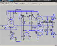
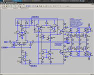
Here is the schematic to my suggestions in post 865. I'm fairly sure it's superior, due to the lack of resonance, and the *d'oh* changing Q2/3 into KSC1845.
As for the regulator, testing at this stage would certainly help but it will matter most when we test it in conjunction with the amplifier itself.
- keantoken
Attachments
Last edited:
Some of you may want to refresh, since I finally edited in the schematic...
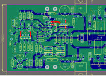
The following has changed (using my schematic numbers). C25 has changed to 1.5u, C27 has changed to 330n. R27 has changed to 12k. The rails only have one bypass each, C21 and C19 which are both 10uF electrolytics. A zobel has been added as R20 and C8.
There will quite possibly be revisions to the rail filtering, when Salas posts.
- keantoken
Hold tight, a more featureful and comprehensive schematic is coming.
Also, if you want output offset below 10mV, assuming all other things balanced, your Jfets will have to be matched within 300uV because of this circuit's high gain.
I'm putting the offset control at the top of the LTP, but this will cause VAS imbalance if your Jfets aren't matched well. On another vein, we could put offset controls at the Jfet degeneration. However this means the VAS (Q1,2/8,7/5,6) and the Jfets should be matched, and that's a lot of matching.
- keantoken
Here it is.
I'd hate for FAA to make a dead fish, so I'm covering all the bases...
- keantoken
ALL the bases ??, how about optional TMC ?? 😱 😎😎
He hee...
OS
Attachments
Last edited:
An oscillator falls in the category of dead fish... And I haven't yet worked out how to choose the values. I'm not gonna give FAA something he might have to troubleshoot with 3 components.
- keantoken
- keantoken
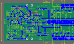
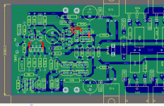
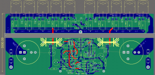
FAA, if you mount your design on a standard heatsink, half of the transistors will be at bottom of heatsink, and other half at top of heatsink
ofcourse you could use a very big custom heatsink, and mount it vertical
but then it wont fit any available box size
its nice, but old style
I suggest to have patience, and give Kean peace and time to focus on what he is doing now
no need to rush it
ofcourse you could use a very big custom heatsink, and mount it vertical
but then it wont fit any available box size
its nice, but old style
I suggest to have patience, and give Kean peace and time to focus on what he is doing now
no need to rush it
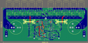
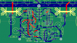
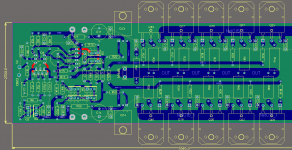
Looking good FAA! I think we should keep it the way it is, short trace lengths and feedback path......should fit on a standard profile heatsink. I would use seperate planes for power and signal and allow the two planes be connected with a small value resistor.
Jam
P.S. I also like the first layout, very similar with I used to do and has some advantages,
Jam
P.S. I also like the first layout, very similar with I used to do and has some advantages,
Last edited:
If you're using TMC, how about including Edmond's "magic pot" to allow cancellation of magnetically induced distortion? Either that or lay out the PCB in such a way as to minimize the effect.... how about optional TMC ?? ...
Example of magic pot is here: http://www.diyaudio.com/forums/solid-state/94676-bob-cordell-interview-negative-feedback-304.html#post2357325
Explanation of problem by Edward Cherry is in attachments here: http://www.diyaudio.com/forums/solid-state/148066-new-cherry-ndfl-amp-3.html#post2104685
- Home
- Amplifiers
- Solid State
- Goldmund Mods, Improvements, Stability