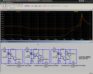
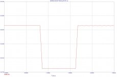
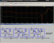
Here are two plots. The first is the output impedance plot using the reactive capacitor, make of it what you will. The second plot is a somewhat more useful pulse behavior plot.
- keantoken
- keantoken
Attachments
Last edited:
because recovery looks a bit faster.....
Hugh
oh
well, I was looking mostly at the small ripples in 2. plot, and their extention
looks smaller and shorter on 2
or maybe those are random
also, looking at 1. plot, the difference between the peak and normal state seems much less
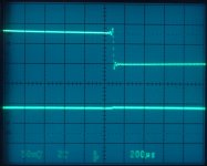
Gotta make and measure. There are many layout, passive parts, and cabling imperfections stuff that will affect step response. Models, hmm, gotta prove their varying quality of accuracy when time subtleties are examined. Here is one pic from an early V1 LV reg of mine as measured by an American member. Top is a transient pulse load, bottom is the DC output reaction. This one is very near to the SSHV as a configuration BTW.
Attachments
Thanks kean,
Puts a few questions I have had to rest. We should be ready to go to board pretty soon if everyone is in agreement.
Jam
Puts a few questions I have had to rest. We should be ready to go to board pretty soon if everyone is in agreement.
Jam
Last edited:
Shunt
Kean,
So what does this prove? Circuit 1 is as good. Here you can see a schematic closer to the real world and load switching between 1 x load and 2 x load. You still have not given an indication of how you derive the impedance looking into the circuit. If you do not know how then why is it important?
I get the feeling that the more complex the better it be.
Attachments
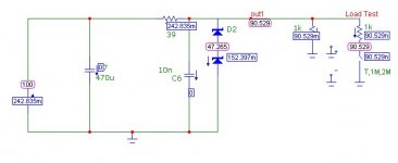
IMO The missing ingredient in all 3 of keentoken's circuits is a damped capacitor across the output to keep the impedance down at HF. Like C6 in Nico's circuit in post 608.
Nico, impedance charts and response graphs emphasize different things to the mind. You can see that the pulse response for all three is about 20mV, nearly all the same in this respect. This is because of the dependence of operation on the cap, which is the primary cause of resonance. The cap has the same response in all 3 circuits. What you may not have noticed is that version 3 has much better DC regulation.
BTW, I use a pulse source with a 10nS risetime, pretty darn fast. Salas, your scope is set to 200uS/div. That makes your risetime several tens of uS? Any reasonably fast circuit won't look bad in this test. Nico, your risetime must be in the hundreds of uS, even easier.
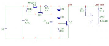
Also, your CCS is sub-optimal. Current will vary with input voltage. Use the CCS arrangement attached.
I don't know what you mean by "derive impedance". Is it more complex than Ohm's law?
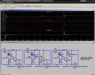
For HF behavior, I think number 2 looks the best. However consider that this is the circuit with the highest impedance. It is easy to make a bad regulator with excellent pulse response - it's a resistor!
If we want to improve pulse response, we need to find a way to dampen the capacitor. After that if more is desired, we would need to cascode something or otherwise thwart Cob/Miller parasitics of the transistors. I think the shunt is already pretty good, and minimal enough to go on the board without much complaint. If we make it complex, it may take up too much board space for those who want to use something different.
- keantoken
BTW, I use a pulse source with a 10nS risetime, pretty darn fast. Salas, your scope is set to 200uS/div. That makes your risetime several tens of uS? Any reasonably fast circuit won't look bad in this test. Nico, your risetime must be in the hundreds of uS, even easier.
Also, your CCS is sub-optimal. Current will vary with input voltage. Use the CCS arrangement attached.
I don't know what you mean by "derive impedance". Is it more complex than Ohm's law?
For HF behavior, I think number 2 looks the best. However consider that this is the circuit with the highest impedance. It is easy to make a bad regulator with excellent pulse response - it's a resistor!
If we want to improve pulse response, we need to find a way to dampen the capacitor. After that if more is desired, we would need to cascode something or otherwise thwart Cob/Miller parasitics of the transistors. I think the shunt is already pretty good, and minimal enough to go on the board without much complaint. If we make it complex, it may take up too much board space for those who want to use something different.
- keantoken
Attachments
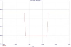
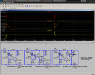
Godfrey, I intentionally simulated without this capacitor to reveal the circuit's true behavior that no cap can fix. Here are simulations with appropriate decoupling.
For the first two regulators, requiring minimal decoupling, the caps used are 10nH, 2mR. The third regulator is decoupled with an electrolytic (15nH, 100mR).
Now that HF behavior is more controlled, we can see in what ways circuit 3 stands out.
- keantoken
For the first two regulators, requiring minimal decoupling, the caps used are 10nH, 2mR. The third regulator is decoupled with an electrolytic (15nH, 100mR).
Now that HF behavior is more controlled, we can see in what ways circuit 3 stands out.
- keantoken
Attachments
Last edited:
BTW, I use a pulse source with a 10nS risetime, pretty darn fast. Salas, your scope is set to 200uS/div. That makes your risetime several tens of uS? Any reasonably fast circuit won't look bad in this test. Nico, your risetime must be in the hundreds of uS, even easier.
- keantoken
That test was done by member jwb on March 2009 on a breadboard. He mentioned ''Transient performance isn't bad either. The top trace is the load signal into a 62R load (about a 25mA load step), and the bottom trace is the regulator output.''. More I don't know.
I don't doubt the circuit has good performance if it is related to SSHV. But to see the circuit's response better you need a faster source risetime.
- keantoken
- keantoken
Last edited:
Jam, I think everyone is okay with the amp schematic, but we may have a lack of volunteers.
- keantoken
- keantoken
I don't doubt the circuit has good performance if it is related to SSHV. But to see the circuit's response better you need a faster source risetime.
- keantoken
You guys will test better when you will make the real amp. Either Nico's or SSHV are very good and low component count to integrate. Nico's is cheaper to make and the parts maybe already in your bins, SSHV needs the Supertex and the K170, some MKPs also, but has error loop gain and its ref is quieter. Take your pick.
We could easily graft your low-noise reference (SK170) onto this shunt. I'm leary of MOSFETs. Your design has much higher DC regulation due to the MOSFET, but I'm thinking may be harder to get stable.
You are right in any case, we can flesh out and improve most parts of the circuit in the simulator, but it needs to be tested in real life. I may be able to do this on the weekend.
- keantoken
You are right in any case, we can flesh out and improve most parts of the circuit in the simulator, but it needs to be tested in real life. I may be able to do this on the weekend.
- keantoken
Nevermind, I don't know anything about the stability of these circuits in real life. However the simulator would seem to indicate that my circuit would be most trouble-free, and less prone to ringing than a MOSFET design. We would need a shunt shoot-out, or we at least choose something that we are familiar with, such as Salas' circuit, so if something goes wrong we know exactly what to do.
Gotta go now. Bye.
- keantoken
Gotta go now. Bye.
- keantoken
How about that to223 part and its heat problem?
Not quite recommended for a Vas.

- Home
- Amplifiers
- Solid State
- Goldmund Mods, Improvements, Stability