I have spent much time and effort on the Goldmund schematic as it appears in the other thread and make the following conclusions. If some have other views please feel free to comment. These are my views only.
The opening thread states as follows:
This thread is to discuss improvements in performance, stability, and reliability.
Among the issues which were brought up:
1: The circuit can be unstable:- This is speculation. Any circuit can be made unstable and there is nothing to suggest that the Goldmund is less stable than any other amp provided it is loaded as specified.
2: Output stage bias has no clear adjustment:- Replace the bias resistor with a trim pot of 1K and bias is adjustable.
3: The topology can be improved:- I think a number of alternative schematics were offered, whether these would be perceived to sound better or worse is debatable.
4: The front end CCS is strange, it is hard to know what it was designed for. A more conventional CCS will be less confusing and more flexible."]Regardless if it is strange or confusing, it obviously works. If anyone is uncomfortable with Goldmund's CCS then replace it with any of those discussed earlier in the thread. Whether this impacts on the perceived sound is hard to tell by just looking at a simulation.
5: Front end rails may have sub-optimal power supply: - They incorporate a separate source with capacitance multiplier, nothing sub-optimal about that.
6: Transistors used don't have adequate voltage specs for the rails: - As far as I can see all the transistors are adequately rated in the application that they are used. Unless for some catastrophic condition all the semiconductors will operate properly.
Several options have been offered to enhance the amplifier using similar topologies. Some have suggested other topologies as well. Kean, it is your thread so concoct one from all the replies that you feel is the best and then make a project of it.
1: Jam contends that the circuit is unstable, and multiple individuals feel the compensation is minimal.
3: This thread is no longer about upgrading the design, but rather seeing to the issues that were brought up against the amp which affect it's useability. IE, no one wants to build amp amp that'll interfere with nearby radio stations.
5: I'm guessing the front rails supply was doubled because of 2 things: it reduces the ripple frequency to 60Hz, and the higher voltage allows for higher source impedance for more effective filtering. This seems pretty logical to me, even worth keeping.
One last thing. I didn't intend to be the sole arbiter of this project. Rather, I felt it was coming and thought I wanted to be part of the team. Even if I offer design support, I won't be able to build the finished design, at least not on anyone's schedule. I also wanted to make a thread where people could openly discuss the design without interfering with the original topic.
That said, I think the best way to increase stability is simply to increase the Cdom cap to 39pF. This is for the frontend. As I've said, I don't know what instability problems may arise from the output stage. I may be able to taylor the frontend to be forgiving about FETs near oscillation, if I knew how to simulate such FETs.
As for preserving the speed of the original, it is almost a given that the speed will suffer if we increase compensation. Less conventional forms of compensation might help. However they can only be confirmed by someone who has built a prototype, since simulation is so vague here. So, my vote is to make a prototype PCB first, optimized for the FETs, and then test out different types of compensation for the frontend.
- keantoken
I think the boards should use source resistors to ensure current sharing between FETs. Those who want to stay truer to the Goldmund design can jumper the resistor pads.
- keantoken
- keantoken
Kean,
sorry I did not mean that you are the arbitrator, what I meant, it is your thread. Concoct a solution from what you figure is valid inputs and post the design for members to pull appart. If you don't take the lead then the thing will just remain a bunch of loose standing items and the thread will eventually die, resulting in nothing.
So take your idea in the front end implement it. Take another's idea to increase compensation, another's to add source resistance, etc.
Kean , design by committee never reaches a final outcome. There has to be a leader or champion that makes things happen.
It has nothing to do with who is the smartest, oldest, wisest, it is a question of herding the cattle to a final destination.
Nico
Krisfr,
Great job. Can you convert it to a PDF so we can enlarge this diagram. This promises to be a pretty outstanding design.🙂
Regards,
Jam
Great job. Can you convert it to a PDF so we can enlarge this diagram. This promises to be a pretty outstanding design.🙂
Regards,
Jam
I am still learning KiCad, It the drawing does not export well.
I am fiddling with it right now. I will try something to get it to pdf or a larger jpg. The limits imposed by DIYAUDIO have to be contended with.
I am working on it...
Thanks
I am fiddling with it right now. I will try something to get it to pdf or a larger jpg. The limits imposed by DIYAUDIO have to be contended with.
I am working on it...
Thanks
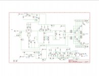
The GoodMund, very nice.
the 10nF are better off close to the drains of each MOSFET and their other leg attached to the heatsink (that one connected to power ground).
the 10nF are better off close to the drains of each MOSFET and their other leg attached to the heatsink (that one connected to power ground).

Kris, that schematic is very unfinished. Where do Q8 and Q9 connect to the input LTP?
Q1, Q2, Q36, Q37, and Q38 are all wrong. C4 and C34 should be across the diodes, not the resistor, and D17 and D3 should be zeners. Shouldn't input ground go to the top of D7/D8, not the bottom?
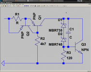
Attached is how the shunt reg should look, pay attention! *cracks whip*
- keantoken
Q1, Q2, Q36, Q37, and Q38 are all wrong. C4 and C34 should be across the diodes, not the resistor, and D17 and D3 should be zeners. Shouldn't input ground go to the top of D7/D8, not the bottom?
Attached is how the shunt reg should look, pay attention! *cracks whip*
- keantoken
Attachments
Got all that, now.
Should Q8 Q9 and Q10 Q11 be matched pair and thermally coupled?
This turning out to be a lot easier since I have gotten up on the learning curve of KiCad a "little"!!!
Keep um coming guys and dolls, I will have this 100% 100% 100% then Alex can treat us all to some REAL eye popping CANDY... and the testing can begin...
Thanks
By the way just HOW do you attach thumbnails pictures to the post of greater than 300K jpgs like Alex does the pc board layouts, I am missing the boat on this somehow...
Last edited:
That ... ummm looks like my CXfet ??? you like. I will will build it first.. 🙂
the heck with alex (awesome software). ("goodmund" ppm??) HA
OS
the heck with alex (awesome software). ("goodmund" ppm??) HA
OS
Krisfr, why not put 10n-100nF decoupling on the collectors of Q15 and Q22?
If you put the offset adjust at R6/R7 rather than the LTP sources, VAS matching won't matter but your FETs will have to be matched. My preference is to match the LTP and use anything for the VAS.
- keantoken
If you put the offset adjust at R6/R7 rather than the LTP sources, VAS matching won't matter but your FETs will have to be matched. My preference is to match the LTP and use anything for the VAS.
- keantoken
- Home
- Amplifiers
- Solid State
- Goldmund Mods, Improvements, Stability