Exactly  !
!
I have to notice a small difference between your schem and the one that I've built, though: The 12AX7's cathode resistors are bypassed capacitively, mine weren't. Hence, it's insufficient bandwith might have had it's cause in the increased output impedance.
Best regards!
!I have to notice a small difference between your schem and the one that I've built, though: The 12AX7's cathode resistors are bypassed capacitively, mine weren't. Hence, it's insufficient bandwith might have had it's cause in the increased output impedance.
Best regards!
Attachments
-
 00CF372B-641C-4AFA-9B31-0907E5C074D1.JPG561.7 KB · Views: 970
 -
 6F815343-1EFA-418B-97A8-B17FF82E99CA.JPG439.3 KB · Views: 947
 -
 0C82389E-9FCF-4140-83EF-B74B180BD1D7.JPG239.8 KB · Views: 988
 -
 A0329056-4A30-43A8-8631-230114C848B3.JPG585 KB · Views: 968
 -
 319A75D6-38F7-4069-BEC4-67224FD3D3A5.JPG418.9 KB · Views: 910
 -
 6E6BB9B4-B328-4E63-AC28-70574BAA559C.JPG301.3 KB · Views: 388
 -
 0DE69A22-258E-46C4-8994-F6E4753AD0F2.JPG455.3 KB · Views: 421
 -
 ABEC9A31-9E66-4B88-93F7-229A85F58431.JPG422.5 KB · Views: 378
 -
 BC52B3FA-C12C-4A8C-85C3-9B215DF6AE70.JPG282.8 KB · Views: 380
 -
 67A0D2D9-B553-453B-A8D1-2C6E933DC7A4.JPG277.7 KB · Views: 379
Attachments
-
 67AC9C23-4221-4466-A69C-2307B4389FB4.JPG315.8 KB · Views: 1,219
 -
 2782644B-1D11-4F4B-90A4-7A00C541EBEF.JPG391.4 KB · Views: 365
 -
 9AD2484C-3F72-46F1-9CED-4E476EDC5CF9.JPG746.4 KB · Views: 469
 -
 25951653-F49A-4F24-B08B-2CAFE47CFD89.JPG429.5 KB · Views: 447
 -
 EA17CBAD-8DBB-4D37-A124-614FEB78215F.JPG369.5 KB · Views: 312
 -
 F68BF2D5-0F29-44EE-A2F9-85458697ED8B.JPG402 KB · Views: 346
 -
 0660DD12-51A3-46A1-9B74-63441070843C.JPG720.9 KB · Views: 419
 -
 097DC94C-2F9A-40FD-AC50-9592B69EC8BE.JPG261.1 KB · Views: 446
December update part II 2017-18 Thanks to Old Radio Boy 🙂
Attachments
-
 081DCBE1-D698-40CD-8664-7AAA8A3F1B89.JPG413.6 KB · Views: 324
 -
 BF08A70D-A026-4EAE-AD62-EF6CA2E79A79.JPG177.2 KB · Views: 295
 -
 D6694652-F0A6-4FA1-AD1C-6B8B75F6AA3E.JPG396.7 KB · Views: 224
 -
 C8140F07-E177-434D-A7F1-E28D691BD72B.JPG406.2 KB · Views: 213
 -
 7D75A011-5565-4765-8C1D-1CABFA6B512D.JPG562.3 KB · Views: 261
 -
 EB1901F0-CC02-47BF-8DDD-A4464B13EFF8.JPG352.9 KB · Views: 367
 -
 F13A686F-FECF-4A68-8BB5-481420CD32C7.JPG353.8 KB · Views: 349
 -
 26C8AD0C-4B74-4F4C-BDA8-9C9517E1F3AB.JPG383.1 KB · Views: 241
 -
 050C7B72-C779-4EB6-BAE4-C5A5CF2F6AB3.JPG577.7 KB · Views: 243
 -
 B42CED28-2D98-4287-B979-AC46AC91BD8E.JPG624.8 KB · Views: 358
Kay Pirinha wrote:
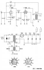
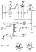
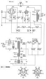
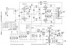
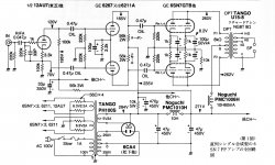
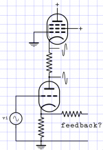
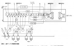
"Can anybody please tell me what the pentode does in this circuit?"
To me it looks like a push-pull configuration.
"Can anybody please tell me what the pentode does in this circuit?"
To me it looks like a push-pull configuration.
Can anybody please tell me what the pentode does in this circuit?
A mu stage?
http://www.fetaudio.com/wp-content/uploads/2003/09/Mu-Stage.pdf
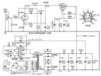
I do not see that as a regulation. Because the signal grid of that pentode, which then must carry some very stable reference voltage, is practically the same as the voltage supplied by that 33uF voltage.
Well, I have to admit this last statement is not at all correct looking at this circuit configuration again so consider this as not written... 😱

Attachments
-
 2EF095AE-2DFD-4FF3-939B-49A3E9D7C33D.JPG342.9 KB · Views: 378
 -
 7960028F-0305-47BA-A990-F0E61A94A39F.JPG256.9 KB · Views: 380
 -
 94CF66F0-1FD1-45AD-A0D1-E3AFF6DFB159.JPG240.6 KB · Views: 698
 -
 0F8C9E17-C374-49D0-829C-3962EC562F49.JPG486.8 KB · Views: 688
 -
 9035BC03-FC12-4186-B0A3-1145EC2611BD.JPG475.5 KB · Views: 693
 -
 EEF7CF40-C6F2-4575-8AF8-4B272C648C26.JPG427.1 KB · Views: 694
 -
 48CA1920-E0E9-4854-B443-758F9DF7656A.JPG263.5 KB · Views: 259
 -
 1734E120-0664-411D-AEAF-45E30ADE02F8.JPG190.9 KB · Views: 255
 -
 C9706572-2267-48F5-8CC5-5507D4352E30.JPG461.5 KB · Views: 325
 -
 6CD947BA-33CE-422F-8395-82F753B5D928.JPG458.5 KB · Views: 328

Anybody knows what happened to Audiophile magazine links?
@ Adason
Better if You are interested download project documentation quickly.
After we will not know if tomorrow they be still available.
"L'Audiophile" archive is down.
Maybe Wayback Machine can help ?
Internet Archive: Wayback Machine
Greetings 🙂
Better if You are interested download project documentation quickly.
After we will not know if tomorrow they be still available.
"L'Audiophile" archive is down.
Maybe Wayback Machine can help ?
Internet Archive: Wayback Machine
Greetings 🙂
Attachments
- Home
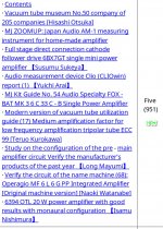
- Amplifiers
- Tubes / Valves
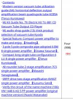
- Gold mine of DI¥ audio tubes schematics from Japan