I've not looked at the APs recently but the old ones did not support AES file 47 (you might say they had a sort of pin 1 problem). At any rate if you decide to check it out, of course neither output terminal can be allowed to be at ground and there really isn't any point of 4 ohm performance (half of the output power is dissipated by the output section itself) and quite a lot for 16 ohms.
The M-60 employs about 2 db of GNFB (our larger amps use none); make sure that a jumper pin is in place between pin 1 and 3 if you are driving it with the RCA input; without the jumper FB will be increased unless driven balanced.
Customers routinely express comments about various brands of 6SN7s used in the amp; we are using the garden variety of Chinese 6SN7 so the distortion can be affected by the driver tube setup. The DC Offset control can affect distortion; if the best setting is not the same as 0volts output it indicates that there is an imbalance in the power tubes which, when corrected, will produce lower distortion.
The amplifier distortion is not tailored in any particular way nor is any compensation employed. The line voltage should be 120VAC, measured at the IEC connection (we have found that a voltage drop across the power cord will affect the the amp).
Does the phase of the moon come into play too???🙂
The man's just sharing some sensible information for someone to test his amp, which he's perfectly willing to have done. I think we could give him a break.
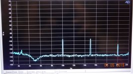
UCD THD+N vs Frequency at 40KHz Bandwidth, plot is valid up to 15KHz.
Now can we stop this Class D can't do more than 6KHz bull or it hides snakes over 6K you need pre analyser AES17 (20K or 40K) filter to stop AP from overscaling not because Class D has killer snakes above 20KHz, besides you can't measure correctly nCore (0.00045 THD+N at 6W) with more than 20KHz Bandwidth, the analyser is 0.0004 THD+N at 80KHz and 0.0002 THD+N at 20KHz.
Except in the datasheets for the ncore you can clearly see the sharp rise in distortion vs frequency that is curtailed rapidly beyond 6.7k due to the measurement bandwidth limitation impacting on its ability to resolve the third harmonic.
Some amplifiers are obviously affected by this far more than others. The ncore is specifically because its midband distortion is so amazingly low. If it wasn't then the rise would be pretty much invisible as it would be swamped out by other forms of non linearity elsewhere within the amplifier.
The man's just sharing some sensible information for someone to test his amp, which he's perfectly willing to have done. I think we could give him a break.

This is Distortion at 100W/8 at 5KHz = .0024% THD of my 200W CFA mosfet amp. The GNFB is about 80 dB from 0 to 20 kHz and it sounds nice according to Richard Marsh http://www.diyaudio.com/forums/solid-state/243481-200w-mosfet-cfa-amp-80.html#post4355552
Damir
Damir
Attachments
Yes, but IMO that is the overall package that wins, not the audio quality of class D...
Having tested a bunch of Class D and A/B amplifiers it is clear that A/B can be better, but also A LOT worse depending on implementation.
There is no reason why class D should not be taking over - it is the better overall solution. but on a single parameter -audio quality- it can be surpassed by a good A/B solution.
Unfortunately the test was done using blind testing, so results are not easy to document.
\\\Jens
I fully agree.. It depends on the application... The result with class D can be good but it takes careful considerations
Ohh yes there was! All these post without thinking, comparing simulations with measurements, talking about class D EMI/RF with absolutely no idea how it is in reality, about class D measurements that 'hide' stuff and filter below 6.5kHz based on not understanding a basic measurement graph is getting tiring.
Seems that anybody is allowed to throw up any keyboard diarrhea (sp) with no need to check facts first. Then when called on it, wiggle out by changing the subject.
You guys are not really into audio at all. You're just into blabbering off the topic of the day.
Sometimes I need to yell, yes! 😡
Jan
Go Yell. I do to when reading this thread....
UCD THD+N vs Frequency at 40KHz Bandwidth, plot is valid up to 15KHz.
Now can we stop this Class D can't do more than 6KHz bull or it hides snakes over 6K you need pre analyser AES17 (20K or 40K) filter to stop AP from overscaling not because Class D has killer snakes above 20KHz, besides you can't measure correctly nCore (0.00045 THD+N at 6W) with more than 20KHz Bandwidth, the analyser is 0.0004 THD+N at 80KHz and 0.0002 THD+N at 20KHz.
Well .. it is because noise starts to dominate when using 80KHz Bandwidth.
But class D is working Hell.
- Inductors in the output stage produces a lot EMI, also the inductors are coupling induviduelly
- Free running class D designs will produce EMI (This is also the case for unshielded SMPS) that will be mixed between the channels and will be seen in the audible range as moving artifacts
- To solve the problem with mixing the switch frequency they offset the switch frequency. For fixed frequency types it is okay. For Free running it does not as the switch frequency change with signal level and load.
- If they are not shielded they will inter-fer with other circuits producing artifacts that we can hear in the speakers.
- Many class D design go for high power... But most likely the S/N ratio is worse than a good designed class A/AB
Filters for measuring class D is to prevent the switch frequency beating the ADC in the measurement equipment. 300KHz on a 182KSamples DAC is not good for the nyquest theory....
It is not just something i have read about....
Last edited:
What does sound best to my ears?
Single gain stage, no multi feedback gain stages....
If we talk voltage feedback it is the inverted configuration with virtuel ground on the noninverted input. For many designs the Jfet input stage is an keeper because of the very low leakage and non existing current noise making it a good choice in high impedance circuits... >5K source impedance.
But the JFET has a highly Vgd depended Crss (Miller capacity). By using it in inverting configuration the voltage across Vgd becomes more or less static.. And you can hear it, regardless of feedback value.
If it is non inverting i will bet on Current feedback as long as we do not talk filters.
The design phase is 1 - 5% simulation, the rest is PCB design, prototyping and testing.
If they are not shielded they will inter-fer with other circuits producing artifacts that we can hear in the speakers.
I have some uCD180 modules, they are not shielded, and there is NO audible noise. Not even with horn tweeters, not even with my ear right at the horn's mouth.
How do inductors in the output produce EMI? They are filters, not generators.
Filters for measuring class D is to prevent the switch frequency beating the ADC in the measurement equipment. 300KHz on a 182KSamples DAC is not good for the nyquest theory....
high OS ratio 64-128x is standard today in delta-sigma audio ADC - do knock it down with a low pass but it doesn't need to be sub lsb
but if you really want to measure class D you should be using MHz sample rate ADC
Digilent Analog Discovery student demo/lab board has a 14 bit 100 Ms/s ADC
Inductors produce magnetic field lines around them.. Depending on the inductor construction it can be less but it is there even with "shielded" types.
RFID technology uses inductors for coupling the LF and HF region.
If you place an sensitive (high impedance of more than 10KOhm) circuit nearby they will pick up noise from the inductors. Try make an 1 turn loop antenna with scope probe and hold it near the inductors, you will be able to see the switch frequence...
high OS ratio 64-128x is standard today in delta-sigma audio ADC - do knock it down with a low pass but it doesn't need to be sub lsb
but if you really want to measure class D you should be using MHz sample rate ADC
Digilent Analog Discovery student demo/lab board has a 14 bit 100 Ms/s ADC
Agree that it does not have to be sub LSB (It is not practical to do), but as you mention it has to be MHz sample rate...
The man's just sharing some sensible information for someone to test his amp, which he's perfectly willing to have done. I think we could give him a break.
Agree. I think there's some questionable ideas there, but the circuit is interesting and the data will speak for themselves.
Inductors produce magnetic field lines around them.. Depending on the inductor construction it can be less but it is there even with "shielded" types.
RFID technology uses inductors for coupling the LF and HF region.
If you place an sensitive (high impedance of more than 10KOhm) circuit nearby they will pick up noise from the inductors. Try make an 1 turn loop antenna with scope probe and hold it near the inductors, you will be able to see the switch frequence...
One remark, don't ever put the inductors in parallel!! In this position the coupling between the inductors are at its best.
But the JFET has a highly Vgd depended Crss (Miller capacity). By using it in inverting configuration the voltage across Vgd becomes more or less static.. And you can hear it, regardless of feedback value.
I love the certainty here. Just in case any of us unwashed unbelievers are not sure of the ears of gold at play. YOU CAN HEAR IT.
I am clearly old and deaf. 🙂
Take the inductors out and then look at emi. Gets much higher at distances beyond inches. The inductor body is too small to be an effective antenna at the relevant frequencies, the close coupling effect is all near field, not radiating.
I love the certainty here. Just in case any of us unwashed unbelievers are not sure of the ears of gold at play. YOU CAN HEAR IT.
I am clearly old and deaf. 🙂
ha ha ha ha ha....
It is not like cables. Try compare with source impedances of ~100k and make an AB comparison of an inverted design with 2x gain and an noninverted with 2x gain as well.
Take the inductors out and then look at emi. Gets much higher at distances beyond inches. The inductor body is too small to be an effective antenna at the relevant frequencies, the close coupling effect is all near field, not radiating.
Nearfield of 10 - 20cm??????? Far enough for me...
It should noted that:-
1. The ncore distortion plots have been done with module powered up from a bench power supply. I am willing to wager that it was with a regulated PSU (linear perhaps?)
2. All of Doug Self's plots in his book ditto - module powered off separate DC supply regulated
It is extraordinarily difficult to get below -110 dBV on mains noise where all the electronics is housed in the same chassis including the PSU.
Last edited:
- Home
- Amplifiers
- Solid State
- Global Feedback - A huge benefit for audio