One other point. If you want to somewhat emulate the 'sound' of a tube amp on SS
1. Remove the output inductor and associated damping resistor
2. In the place of the inductor, insert a 2 Ohm 10 Watt resistor
The effects seem much more pronounced on larger, vented speakers.
1. Remove the output inductor and associated damping resistor
2. In the place of the inductor, insert a 2 Ohm 10 Watt resistor
The effects seem much more pronounced on larger, vented speakers.
ha ha ha ha ha....
It is not like cables. Try compare with source impedances of ~100k and make an AB comparison of an inverted design with 2x gain and an noninverted with 2x gain as well.
You can't move the goalposts at the first challenge. You said 'Regardless of feedback value'.
Certainly a bench supply will be linear-regulated I should think, possibly for very high-power ones with a switching preregulator. But who knows. I guess the specific supplies should be disclosed.It should noted that:-
1. The ncore distortion plots have been done with module powered up from a bench power supply. I am willing to wager that it was with a regulated PSU (linear perhaps?)
...
It is extraordinarily difficult to get below -110 dB on mains noise where all the electronics is housed in the same chassis including the PSU.
I haven't played with the amps for some years now, but I believe Bruno put a good deal of effort into coming up with SMPSs specifically to work with his amplifiers and in particular to address the problem of rail pumping with single-ended ones. Whether these were deployed for any of the nCore measurements or not I don't know. Of course one is inclined to suppose a good linear regulator would be superior to a switcher, although Hofer despite his initial skepticism did find switchers suitable for the latest Audio Precision analyzers, and told me that a crucial ingredient was sourcing a very good common-mode choke.
Of course the AP loads are relatively small and fairly time-invariant compared to a power amplifier.
The Crown switchmode amps use switchers for the power supplies, and I believe there is a good deal of interaction based on the anticipated instantaneous demands of the output stages. Gerald Stanley mentioned that they have a bit of look-ahead capability based on a fairly-high-order Bessel filter near the input with a rolloff around 30kHz. Although the effort to do a Levinson-branded class I (for Interleave, not just the next letter after H) power amp met with a lukewarm critical reception from Stereophile, the products certainly work well according to many criteria. I believe, in order to sidestep issues with any distortions arising from the output inductors, the ones used were air core toroids. The circulating currents are probably quite high, as the amplifier apparently gets pretty warm.
I recall the effective switching frequency of the Levinson was 4MHz. I was going to tease Hofer about how it's once again demanding a still-wider bandwidth AP.
Last edited:
One other point. If you want to somewhat emulate the 'sound' of a tube amp on SS
1. Remove the output inductor and associated damping resistor
2. In the place of the inductor, insert a 2 Ohm 10 Watt resistor
The effects seem much more pronounced on larger, vented speakers.
Carver did something like that and called it a "current-source" output. The normal output was still available.
Eliminating common-mode distortion is always a good idea, but the direct approach entails rather low impedances and consequent source loading if noise is to stay low.What does sound best to my ears?
Single gain stage, no multi feedback gain stages....
If we talk voltage feedback it is the inverted configuration with virtuel ground on the noninverted input. For many designs the Jfet input stage is an keeper because of the very low leakage and non existing current noise making it a good choice in high impedance circuits... >5K source impedance.
But the JFET has a highly Vgd depended Crss (Miller capacity). By using it in inverting configuration the voltage across Vgd becomes more or less static.. And you can hear it, regardless of feedback value.
If it is non inverting i will bet on Current feedback as long as we do not talk filters.
The design phase is 1 - 5% simulation, the rest is PCB design, prototyping and testing.
Perhaps various forms of cascoding would invalidate your single-stage criterion, but can be quite effective in reducing effects of variable Cgd, as well as thermal distortions.
Basic comparison of THD spectrum ,
A class - JLH1969 vs a/B class - Arcam Alpha 8P , two different static load , 8,2-ohm vs 15-ohm .
Your comments ?
I listened to a JLH amp once, my friend was using a 300 watt phase linear amp and then switched over to the JLH. The difference was night and day - the JLH amp KILLED the phase linear.
never heard an Arcam Alpha 8P so i wonm't say anything about it.
But the graphs do show that the JLH has a nicely decreasing distortion spectrum, which probably accounts for the great sound.
The amount of nonsense in this thread is just WOW!
"Many class D design go for high power... But most likely the S/N ratio is worse than a good designed class A/AB"
--NC1200 module 28 microvolts 20khz bandwidth -103db at 2.8V unweighted that is state of the art performance better almost any Class AB amp on the market (UCD700LZ OEM 35 microvolts 20Khz unweighted)
"Free running class D designs will produce EMI (This is also the case for unshielded SMPS) that will be mixed between the channels and will be seen in the audible range as moving artifacts"
--EMI happens in from bad board design problem that was solved in 2004 you can test any UCD board this is not rocket science all you need is a analog scope if you wanna go fancy you can use RF test gear no problem you not gonna find EMI problems.
"Inductors in the output stage produces a lot EMI, also the inductors are coupling induviduelly"
--This is just plain stupid....
"If they are not shielded they will inter-fer with other circuits producing artifacts that we can hear in the speakers."
--Artifacts are a product of a bad design you can not shield EMI problem it comes out the speaker wire
"Filters for measuring class D is to prevent the switch frequency beating the ADC in the measurement equipment. 300KHz on a 182KSamples DAC is not good for the nyquest theory...."
--Complete nonsense AP 2700 uses Cirrus Logic chip that samples at 6MHz and uses digital filtering, the problem with 2700 is that the input signal triggers the range detector in the analog domain then it goes to the ADC and modern Class D switch at 350khz filtered by second order filter with cutoff at 35khz residual is 40db down on fundamental and 3rd harmonic will be 29db down from the fundamental so the switching residual looks like sine wave with 350 milivolts at 350khz, so if you test THD+N at 300 milivolt sinewave the AP see 300+350milivolts and activate the 600milivolt range on the scale so you always get the wrong numbers on the THD scale that is why you need to activate AES17 pre analyser filter to reduce that 350milivolt residual so you can get real numbers on the scale
5th element "Except in the datasheets for the ncore you can clearly see the sharp rise in distortion vs frequency that is curtailed rapidly beyond 6.7k due to the measurement bandwidth limitation impacting on its ability to resolve the third harmonic."
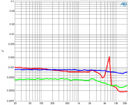
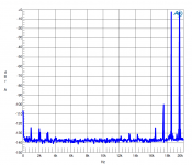
Ncore design has loop gain of 53db up to 6khz then goes up to 65db (pole) at 15khz then back to 53db at 20Khz when driven hard distortion around 6-10KHz climb a little but then it drops down around 20Khz and it stays low until 40Khz then is climbs up to 70khz but in a lesser manner than any Pass Labs Krell or whatever you clame to be superior and it hovers in a low feedback mode up to 200khz it does not fall apart at ultrasonics and it does not intermods into the audio band you can see from the IMD plot.
..THD+N vs Hz - Blue 2W(Thermal) , 20W Green , 200W red--4Ohm 20Khz band
..IMD 50w and 50w peak 200 W Sine 4Ohm
"Many class D design go for high power... But most likely the S/N ratio is worse than a good designed class A/AB"
--NC1200 module 28 microvolts 20khz bandwidth -103db at 2.8V unweighted that is state of the art performance better almost any Class AB amp on the market (UCD700LZ OEM 35 microvolts 20Khz unweighted)
"Free running class D designs will produce EMI (This is also the case for unshielded SMPS) that will be mixed between the channels and will be seen in the audible range as moving artifacts"
--EMI happens in from bad board design problem that was solved in 2004 you can test any UCD board this is not rocket science all you need is a analog scope if you wanna go fancy you can use RF test gear no problem you not gonna find EMI problems.
"Inductors in the output stage produces a lot EMI, also the inductors are coupling induviduelly"
--This is just plain stupid....
"If they are not shielded they will inter-fer with other circuits producing artifacts that we can hear in the speakers."
--Artifacts are a product of a bad design you can not shield EMI problem it comes out the speaker wire
"Filters for measuring class D is to prevent the switch frequency beating the ADC in the measurement equipment. 300KHz on a 182KSamples DAC is not good for the nyquest theory...."
--Complete nonsense AP 2700 uses Cirrus Logic chip that samples at 6MHz and uses digital filtering, the problem with 2700 is that the input signal triggers the range detector in the analog domain then it goes to the ADC and modern Class D switch at 350khz filtered by second order filter with cutoff at 35khz residual is 40db down on fundamental and 3rd harmonic will be 29db down from the fundamental so the switching residual looks like sine wave with 350 milivolts at 350khz, so if you test THD+N at 300 milivolt sinewave the AP see 300+350milivolts and activate the 600milivolt range on the scale so you always get the wrong numbers on the THD scale that is why you need to activate AES17 pre analyser filter to reduce that 350milivolt residual so you can get real numbers on the scale
5th element "Except in the datasheets for the ncore you can clearly see the sharp rise in distortion vs frequency that is curtailed rapidly beyond 6.7k due to the measurement bandwidth limitation impacting on its ability to resolve the third harmonic."
Ncore design has loop gain of 53db up to 6khz then goes up to 65db (pole) at 15khz then back to 53db at 20Khz when driven hard distortion around 6-10KHz climb a little but then it drops down around 20Khz and it stays low until 40Khz then is climbs up to 70khz but in a lesser manner than any Pass Labs Krell or whatever you clame to be superior and it hovers in a low feedback mode up to 200khz it does not fall apart at ultrasonics and it does not intermods into the audio band you can see from the IMD plot.
..THD+N vs Hz - Blue 2W(Thermal) , 20W Green , 200W red--4Ohm 20Khz band
..IMD 50w and 50w peak 200 W Sine 4Ohm
Attachments
Brad, thanks for the comments. Rail pumping is certainly an issue n class D. My commr nets were however targeted at the remarkably clean noise and distortion plots on both the ncore and on DS's plots.
Ncore plots and noise measurments are done using Hypex unregulated SMPS1200 and SMPS600.
Ncore PSRR 80db f<1kHz.
Ncore PSRR 80db f<1kHz.
https://www.youtube.com/watch?v=U_eZmEiyTo0
Would you like to try the AB test?
Clearly, I don’t need to take the AB test, as I have posited that all amplifiers sound the same.
What if we make it interesting, say a lifetime membership to AES?
Very well, I accept. But since we already know that I will not be able to hear a difference, I will deduce the answer with my superior powers of reasoning alone.
Alright, but I’m not sure what you mean.
But it's so simple. All I have to do is divine it from what I know of you: are you the sort of man who would connect the tube amplifier to the speakers, or the solid state. Now, a clever man would connect the solid-state amplifier because he would know that all amplifiers sound the same anyway, and a so-called golden-eared audio fool, trying to hear a non-existent difference, would almost certainly guess the tube amplifier because he is incapable of escaping his own bias.
Truly, you have a dizzying intellect.
Oh, I’m just getting started. However, since I am clearly not an audio fool, and doubtless you recognize this, it is possible that you have connected the tube amplifier, hoping that your choice will throw me off since you know that I know that all amplifiers sound the same and would guess that you’ve chosen the amplifier most commonly (but wrongly) thought of as being more neutral and less colored.
I see.
Yet still, you and your new age crystal-gazing ilk cling to the notion that low order harmonic distortion might somehow be audible, and I doubt that you could set aside your precious theories long enough to apply reverse-psychology to this experiment despite the high stakes, and so, believing that feedback is bad, despite the fact that I have proven that it is good because it reduces distortion, which I have likewise skillfully (and with citations) argued to be completely inaudible, I must therefore conclude that you have connected the solid-state amplifier.
Look! What in the world can that be?
Just a little harmless comic relief, guys 🙂
LOL 😀 Exactly, sums this whole discussion up perfectly. Love that movie and that's the best scene, (despite the charming references to my home country)...
Ncore plots and noise measurments are done using Hypex unregulated SMPS1200 and SMPS600.
Ncore PSRR 80db f<1kHz.
Not in the same box. Trust me.
Yes. The sad thing is most of the hand-waving and hypothesizing is done tacitly assuming quasi-linear. If we start to really dig in to nonlinear systems things get hairy in a hurry. But doing so, I can see where we'll just unleash a herd of terms that will be taken up by people and cited to justify mostly-pseudoscience.
Quasi-linear works fine, and although not automatically leading to insights, fine-enough-mesh simulators and good device models work well with nonlinear systems, absent "catastrophes".
An example is the famous Black feedback equation itself. Although often quoted as Gospel, it's an approximation that assumes a linear amplifier.
Thanks as always,
Chris
As a matter of interest how much gain is needed at 60KHz to deal with the crossover distortion?
A good case can be made that feedback *cannot* deal with crossover distortion, by analogy to the worst case: During a period when the amplifier is not conducting, no output occurs and no linearity correction is made.
Crossover distortion is the too often unspoken flaw of most modern amplifier design. Made worse by believing in monotonicity that ain't there.
Thanks,
Chris
One big advantage of class D - no crossover distortion equivalent. Its all just duty cycles, nothing special about waveform portions near zero volts, tgat just happens to be 50% duty cycle.
One big advantage of class D - no crossover distortion equivalent. Its all just duty cycles, nothing special about waveform portions near zero volts, tgat just happens to be 50% duty cycle.
Well, most class D has something similar: The deadtime between switching the active element off and turning the other on takes time (It must or the power stage will cross conduct)
Deadtime is important for audio quality.
Alternative power stages are starting to emerge....
\\\Jens
A good case can be made that feedback *cannot* deal with crossover distortion, by analogy to the worst case: During a period when the amplifier is not conducting, no output occurs and no linearity correction is made.
Crossover distortion is the too often unspoken flaw of most modern amplifier design. Made worse by believing in monotonicity that ain't there.
Thanks,
Chris
This is why you need a class A part of the signal to be present at all times, so you're not dependent on turned off class B bjt's to correct the signal.
You can't move the goalposts at the first challenge. You said 'Regardless of feedback value'.
No i do not change my goalposts, but i wanted to state an example where it would be very easy to hear the difference.
Eliminating common-mode distortion is always a good idea, but the direct approach entails rather low impedances and consequent source loading if noise is to stay low.
Perhaps various forms of cascoding would invalidate your single-stage criterion, but can be quite effective in reducing effects of variable Cgd, as well as thermal distortions.
You are right, but if you want to make an transformer less front end for balanced input, inverting mode with two opamp's shows a lot better CMRR than using them in noninverting mode.
i also stated that if you want to use them in high impedance circuit (i think i did write >5Kohm!??), i think i also wrote that the jfet inputstage will be a benefit with there low leakage and non existing current noise...
It is all a matter of choices to be made.
The amount of nonsense in this thread is just WOW!
"Many class D design go for high power... But most likely the S/N ratio is worse than a good designed class A/AB"
--NC1200 module 28 microvolts 20khz bandwidth -103db at 2.8V unweighted that is state of the art performance better almost any Class AB amp on the market (UCD700LZ OEM 35 microvolts 20Khz unweighted)
I did not write all, Hypex is in general very good, but still for monitoring purpose in studios one of my customers changed from hypex UCD400 to my design and ended up with less audible noise from the speakers
"Free running class D designs will produce EMI (This is also the case for unshielded SMPS) that will be mixed between the channels and will be seen in the audible range as moving artifacts"
--EMI happens in from bad board design problem that was solved in 2004 you can test any UCD board this is not rocket science all you need is a analog scope if you wanna go fancy you can use RF test gear no problem you not gonna find EMI problems.
All CE test is most likely to be done in a shielded box to get them through the tests. I have measurement equipment here for the purpose
"Inductors in the output stage produces a lot EMI, also the inductors are coupling induviduelly"
--This is just plain stupid.... No it is not, again use an H-field probe. Also if you do an sweep up to 30MHz, you will clearly see the switch frequency and its harmonics.
"If they are not shielded they will inter-fer with other circuits producing artifacts that we can hear in the speakers."
--Artifacts are a product of a bad design you can not shield EMI problem it comes out the speaker wire
No i am not talking speaker wires here my friend, but class D has very high dv/dt values, and to save money many designs is only a 2 layer pcb. I know that IRF reference designs are two layer, but they have massive ground copper layers. But still you have the EMI which could be lowered a lot by using 4 layer and use the layers as shields.
"Filters for measuring class D is to prevent the switch frequency beating the ADC in the measurement equipment. 300KHz on a 182KSamples DAC is not good for the nyquest theory...."
--Complete nonsense AP 2700 uses Cirrus Logic chip that samples at 6MHz and uses digital filtering, the problem with 2700 is that the input signal triggers the range detector in the analog domain then it goes to the ADC and modern Class D switch at 350khz filtered by second order filter with cutoff at 35khz residual is 40db down on fundamental and 3rd harmonic will be 29db down from the fundamental so the switching residual looks like sine wave with 350 milivolts at 350khz, so if you test THD+N at 300 milivolt sinewave the AP see 300+350milivolts and activate the 600milivolt range on the scale so you always get the wrong numbers on the THD scale that is why you need to activate AES17 pre analyser filter to reduce that 350milivolt residual so you can get real numbers on the scale
5th element "Except in the datasheets for the ncore you can clearly see the sharp rise in distortion vs frequency that is curtailed rapidly beyond 6.7k due to the measurement bandwidth limitation impacting on its ability to resolve the third harmonic."
Ncore design has loop gain of 53db up to 6khz then goes up to 65db (pole) at 15khz then back to 53db at 20Khz when driven hard distortion around 6-10KHz climb a little but then it drops down around 20Khz and it stays low until 40Khz then is climbs up to 70khz but in a lesser manner than any Pass Labs Krell or whatever you clame to be superior and it hovers in a low feedback mode up to 200khz it does not fall apart at ultrasonics and it does not intermods into the audio band you can see from the IMD plot.
..THD+N vs Hz - Blue 2W(Thermal) , 20W Green , 200W red--4Ohm 20Khz band
..IMD 50w and 50w peak 200 W Sine 4Ohm
Not in the same box. Trust me.
You are very right about it.
Well, most class D has something similar: The deadtime between switching the active element off and turning the other on takes time (It must or the power stage will cross conduct)
Deadtime is important for audio quality.
Alternative power stages are starting to emerge....
\\\Jens
exactly, also if you look on the waveform of the output before the filter you will see that the fall and rise time is not identical and if the design if not good enough then the rise and fall is not linear, will have ringing that is not identical.
- Home
- Amplifiers
- Solid State
- Global Feedback - A huge benefit for audio