Can somebody please help answer this. The extra cap pair to sort the buzz problem, would 220uF do ?
I've installed the pair of 220uF caps at C4. Have a new problem though - R7 gets really hot. One of them started to turn brown. Thinking it could be a faulty part I replaced with a new R, same problem.
I've also posted this in a thread for my ACF-2 build. Sorry about the repeat.
I've installed the pair of 220uF caps at C4. Have a new problem though - R7 gets really hot. One of them started to turn brown. Thinking it could be a faulty part I replaced with a new R, same problem.
I've also posted this in a thread for my ACF-2 build. Sorry about the repeat.
Attachments

Yes, that is the way to connect the two caps.
Thanks to Sunil, I just realized that the connection shown in post #74 above is wrong - sorry I did not notice it the first time. The cap connected between the ground and R7 - that's the left cap on the photo in post #74 and the one close to the board's edge in sunil's post above, should be reversed, as R7 is the negative rail. Connected as shown, the cap may short the negative rail, burn R7, and possibly explode.
Last edited:
It works. Got a new set of caps and wired them the right way around.
It is quiet. I'm running very efficient Altecs and there is absolutely no HUM, compared to earlier, without the twin-cap mod.
Thanks alexcp.
It is quiet. I'm running very efficient Altecs and there is absolutely no HUM, compared to earlier, without the twin-cap mod.
Thanks alexcp.
Hi Sunil could please post the closer pics and the capacitors values used.
Me too want to try with my Akido octal buffer.
Regards
Me too want to try with my Akido octal buffer.
Regards

I have finished this project over this last weekend and have low frequency hum. I have reached out to JB and he had a few suggestions, however they require more modifications than what is suggested in this thread. I would like to try the twin cap method first. I am curious though, how is the value of the Electrolytic caps used determined or calculated? Alex used 470uf and Sunil is using 220uf. Is there any reason to use so much capacitance or would small values work as well? I have found small value electrolytics at mouser that have a much higher voltage rating. I would like to understand as much about this modification as possible. If anyone can shed some light on this I would appreciate it.
It would be useful for everyone if you shared JB’s suggestions.
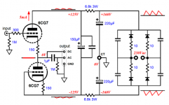
The ACF -2 circuit “Aikido” feature relies on the ground referenced hum from the positive power supply rail cancel that from the negative supply rails - see the attached picture (from JB) and the complete discussion at tubecad.com. I find the idea quite elegant in its simplicity.
However, in practice the hum from one rail does not cancel that from the other rail. This may happen because of, for example, tolerances of C18/19 or the power transformer’s secondary windings.
The suggested remedy is to further filter each rail with an ground referenced RC filter instead of the differential R4/R7/C4/C5. It is convenient on JB’s PCB to split C4 and ground the middle point. Each cap (let’s call them C4A and C4B) forms an RC filter with R4 or R7, respectively, and attenuates hum on its rail. The value of each cap defines the time constant of the filter and thus the attenuation. The more capacitance, the more hum is attenuated. Small caps will work, too. They will not be as effective, but may be effective enough for your purpose. There are also practical limits on how big a cap you can fit on the PCB.
Attachments
Alex, thank you for the reply. Your explanation of the function of the RC filter and why it attenuated the hum is very helpful. Of course I want to be sure to choose the the most suitable values for these caps that will not degrade the sound, but eliminate the hum. Is there a measurement a builder can take that would allow them to calculate the correct amount of capacitance to cancel the hum? Or am I reading to far into this?
Alex, You mentioned the time constant of the filter being defined by the value of the cap. I will have to read up on this, perhaps it will answer my question.
I will summarize JB’s reply later this afternoon when I have more time.
Alex, You mentioned the time constant of the filter being defined by the value of the cap. I will have to read up on this, perhaps it will answer my question.
I will summarize JB’s reply later this afternoon when I have more time.
One way to think about an RC filter is to realize it is a voltage divider. As the capacitor has lower impedance at higher frequencies, the attenuation of such a divider depends on frequency.
Let’s say we split C4 in two caps, with C4A connected between the positive rail and the ground, and C4B - between the negative rail and the ground. In the case of the positive rail, the divider is then formed by R4 and C4A. You can look up the relevant math online, but the result is that the attenuation of such a divider equals sqrt(1+(2*pi*freq*R*C)^2) - that is, the higher the frequency, the higher is the attenuation. The attenuation is also proportional to C - the more capacitance you have, the higher is the attenuation at any given frequency.
Say we have R=6.8kOhm and C=220uF. Our frequency of interest is 120Hz. The attenuation then is sqrt(1+(2*pi*120*6800*0.00022)^2) = 1128, if my math is correct. So the RC filter with the above values reduces 120Hz hum by a factor of roughly 1000, or by 60dB, so 1mV of hum becomes 1uV. C=470uF will bring it to 2000, while C=22uF - to 100.
Obviously the rail noise is not the only source of noise in your system, so you don’t want to keep filtering your rails to infinity. At some point other sources will dominate, so the return on extra capacitance will be diminishing. That would probably be your optimal capacitance.
In practice, however, 60dB sounds like an improvement, especially if you have handy those 220uF caps, rated for correct voltage.
Last edited:
Alex, thank you again for your in depth explanation. The function of the filter makes sense, but I definitely need to brush up on my math.
When I inquired about the cap mod and low level hum, JB said the best solution is to replace R12 to R15 with jumper wires and then place a 100 to 1k ohms resistor in series with the secondary center-tap and the PCB's ground pad. Better still, would be to use a choke in place of the series resistor.
He said he has never encountered a miss tapped secondary, but if he did, he would use a choke to absorb the imbalance.
I will say JB has been very helpful, and the boards I have purchased from him are very, very nice.
Thank you! JB’s a clever solution. He creates an RC (or LC, which is even better) filter with that series resistor/choke and C18/C19, with the effect similar to what I described above. Very clever.
JB’s suggestion is compatible with mine; they can be used together for even better filtering.
BTW, while mistapped secondary may be rare, mismatched electrolytic capacitors are common - they usually have 20% tolerance, and the capacitance changes with time and temperature. With 5mA anode current and C18/C19 = 220uF, the sawtooth wave on each of C18 and C19 (without a series resistor/choke you described) would be about 350mV peak to peak (R12-R15 reduce it somewhat). A 1% mismatch between C18 and C19 would produce 3.5mV of imbalance between the positive and negative rails. In ACF-2, 50% of that imbalance goes to the output - that’s 1.75mV of hum not cancelled by JB’s Aikido - and can be easily audible. Larger mismatch would produce more hum.
Hi everyone
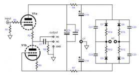
please, what are the values of R8/R9 in the ACF-2 schematic? Tube are 12AU7.
In ACF-2 manual this values are not indicated.
Besides also where it should be connected the Href?
See Image attached.
Sorry, but it's my first tube application😱
Thanks
please, what are the values of R8/R9 in the ACF-2 schematic? Tube are 12AU7.
In ACF-2 manual this values are not indicated.
Besides also where it should be connected the Href?
See Image attached.
Sorry, but it's my first tube application😱
Thanks
Attachments
Href is the filament supply reference. Connect the filament supply negative (DC) here. R 8 and R9 are not that critical. Try about 200K to 300K, 1 watt. Both should be the same value.
Steve
Steve
Er, not quite. The idea is to put the heater at the potential within the tube's acceptable heater-to-cathode voltage range. Since the bottom triodes on the schematic operate with their cathodes close to B-, and the top ones - with cathodes close to the ground potential, the usual approach would be to place the heater somewhere around half of B- (the exact value is not critical). To quote JB:
If you make R8 and R9 equal, the heater will be halfway between B+ and B-, that is, at ground potential, and you risk exceeding the maximum heater-to-cathode rating. That said, some manufacturers put the rating at 200V of any polarity, so ground potential for the heater may be ok. In this case, you wouldn't need C7, R8 and R9 - just short C7 and connect the negative side of the heater directly to the ground.
The resistors' values should be large (100s of kOhms) to keep the current through them, and their power dissipation, low. For example, R8 can be 100kOhm and R9 - 300kOhm. Or 300kOhm and 910kOhm.Since one triode stands atop another, the heater-to-cathode voltage experienced differs between triodes. The safest path is to reference the heater power supply to a voltage equal to one half the B- voltage; for example, -50V, when using a +/-100V power supply. This voltage ensures that both top and bottom triodes see the same magnitude of heater-to-cathode voltage. Resistors R8 & R9 establish this voltage relationship.
If you make R8 and R9 equal, the heater will be halfway between B+ and B-, that is, at ground potential, and you risk exceeding the maximum heater-to-cathode rating. That said, some manufacturers put the rating at 200V of any polarity, so ground potential for the heater may be ok. In this case, you wouldn't need C7, R8 and R9 - just short C7 and connect the negative side of the heater directly to the ground.
Thank you alexcp
please can you post here the pdf's documents that you posted in the page:
Removing hum from Aikido Cathode Follower (ACF-2 9-Pin) - diyAudio
these cannot be opened or corrupted.
Thanks again
please can you post here the pdf's documents that you posted in the page:
Removing hum from Aikido Cathode Follower (ACF-2 9-Pin) - diyAudio
these cannot be opened or corrupted.
Thanks again
Apologies for the slow reply. I did not keep the original PDFs, so I had to re-create them. Here you go.
A quote from my own (sorry!) blog post:
Also, JB himself proposed a different hum fix, see posts #94-95 above.
A quote from my own (sorry!) blog post:
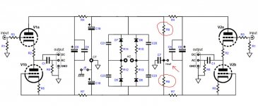
One solution would be to split C5 (UPDATE: or C4) into two capacitors each, one connected between B+ and the ground, the other between B- and ground - see the attached schematic. That wouldn't eliminate any mismatch but would make it less relevant, as there would be a lower impedance path for the signal current to ground from the anode of U1a (U2a) and the bottom end of R5. The PCB is not designed for this, unfortunately, but one can place two radial capacitors in the space allocated for C4, connecting them to C4 pads and to the ground pad nearby. I ended up installing 2x 470uF 200V caps in each channel and leaving in place C5. This reduced the hum from 0.15% to ~0.001%.
Also, JB himself proposed a different hum fix, see posts #94-95 above.
Attachments
Last edited:
- Home
- Amplifiers
- Tubes / Valves
- Glassware ACF-2 Aikido hum problem