There is no final schematic, just my idea for topology and 'borys' made his working prototype with this schematic (measurements is in post #111)
I don't say it won't work , you just don't need the miller comp. at cascoded
VAS.
I built a luxman cascoded VAS with double green diodes referenced
from rail to rail. It "sang" very nicely , but with more difficult loads - an EF2
won't do.
Using a EF2 with lateral FET's or an EF3 would allow a VAS to "sing"
freely with little loading.
On the subject of intentional loading (R23-24 on the GLA) ,this preloads
the VAS, making an external load (such as the output stage) less
of a factor over a wider range. It is also a convenient way to "trim" the
loop gain of the entire amplifier. (lower H3/5 as well.)
OS
I suggest TEF output stage in post #41, and cascoded VAS referenced from rail to rail need only one resistor 🙂
I will copy-paste your post to my thread for help 'borys' to made beter amp.
Regards
I suggest TEF output stage in post #41, and cascoded VAS referenced from rail to rail need only one resistor 🙂
I will copy-paste your post to my thread for help 'borys' to made beter amp.
Regards
I'm not being sarcastic , but "better amp" is the goal of all DIYA.
Mr.(Dr.) bora 's designs were quite helpful for me to learn the way of the
VFA amp. There are some members that have "left" DIYA , but allowed me to
understand and manipulate the bode plot for amplifiers.
I can't make an oscillator (unless I wanted to) this is a "craft" that carlos
and others must master. (I don't mean this in a bad way)
OS
...There are some members that have "left" DIYA , but allowed me to
understand and manipulate the bode plot for amplifiers...
Would be great if you would share some of these compensation developing techniques.
I've been struggling with compensation with my amp for about 2 months now, still trying to get advice.
Regards
That makes me happy. So, with the bypass in place, we didn't inflate the esr of the feedback-shunt's cap by 10R more. Treble problem solved! Really nice. Thanks.yes , that is a good idea. I used a bypass across the 10R to mitigate PC power supply noise in an earlier amp project. A .1uf multilayer ceramic was used . OS
I'm not being sarcastic , but "better amp" is the goal of all DIYA.
Mr.(Dr.) bora 's designs were quite helpful for me to learn the way of the
VFA amp. There are some members that have "left" DIYA , but allowed me to
understand and manipulate the bode plot for amplifiers.
I can't make an oscillator (unless I wanted to) this is a "craft" that carlos
and others must master. (I don't mean this in a bad way)
OS
Once you understand Bode plots, compensation becomes second nature. Some topologies lend themselves to a simple dominant pole, others do not. More stages mean staggering poles and zeros. The $64k question is - where are they? The REAL trick is being able to estimate the Bode plot (at least asymtotically) with NO or INCORRECT models. If you have a perfect model, then you can plug it in and let the computer calculate everything. Most times you do not.
It occurs to me that the losses of the CRC filter should located upon the amplifier board, series to the dc power cable. Instead of resistor at amp board power taps, try 10a1 or 6a05, because, predictable. This rearrangement would require at least 440u per each rail at the amplifier board for steady. However, it also allows the power supply board's big caps to charge, recharge, recover at full speed so you get a whole lot more dynamic bass slam (when no losses at power board, then transformer amperage is not wasted).
SO, if you have one modest little transformer and one Simple (non-crc) power board available for this project, try it.
Cost:
4 of 10a1 (two per amp board, on the amp board, series to power cable)
4 more of 220u (the schema only 220u per rail, so double up to 440u)
Less cost at smaller amp enclosure (with 1 transformer 1 power board)
P.S. There's more to say about it, but the doing works better than the typing. Success varies with topology.
The REAL trick is being able to estimate the Bode plot (at least asymtotically) with NO or INCORRECT models. If you have a perfect model, then you can plug it in and let the computer calculate everything. Most times you do not.
Most times? Maybe not?
At my site's DIY tools menu Start! Fetch! <--link select "LT Spice Models (right-click, save as)" and note that model names that have an extension like "K" or "C" have been quality controlled. An RC calculator is also provided on that same menu just in case anyone wants to get their feedback-shunt RC value down below 0.444hz for high resolution bass clarity. Someday, I'd like to see that. Was hoping for sooner. Anyway, stuff is there if you want it.
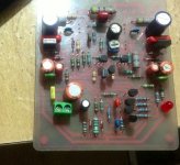
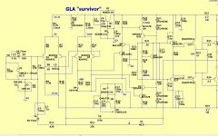
GLA SURVIVOR amp
Hi Ostripper
greetings i cant get 220uf NP in market should i go with ordinary 220uf
or
use 2 470 uf and make it non polar its a rough pcb only for test i will make the pcb as you have suggested
warm regards
andrew😉
Hi Ostripper
greetings i cant get 220uf NP in market should i go with ordinary 220uf
or
use 2 470 uf and make it non polar its a rough pcb only for test i will make the pcb as you have suggested
warm regards
andrew😉
Attachments
Once you understand Bode plots, compensation becomes second nature. Some topologies lend themselves to a simple dominant pole, others do not. More stages mean staggering poles and zeros. The $64k question is - where are they? The REAL trick is being able to estimate the Bode plot (at least asymtotically) with NO or INCORRECT models. If you have a perfect model, then you can plug it in and let the computer calculate everything. Most times you do not.
I don't ALWAYS trust the simulator. I've even gone to the length of sticking
tian probes into individual sections of the amp.
But even with all this computational "goodness" , having the original REAL
amp to fall back on is a godsend.
The simulation with Sansui's compensation shows an unconditionally stable,
well behaved amp .... 32 years and playing now- while I type - all original
Toshiba and Sanken devices.
I've "swapped" many models for the LTP(s) , the VAS ... all result in a
very similar bode plot , this indicates that the compensation is at least
slightly independent of models used.
A higher gain Zetex vs a standard KSA992 shows almost NO difference(below 1/2).
Try this on a blameless ! - loop gain increases by 10db and the margin needs
to be re-compensated.
My take on this amp increases the margin by a few degrees and uses
better regulation for the differentials (Q1-4).
Being a low end consumer offering , Sansui even uses(stole😀) the preamp's
negative supply for the front end.
The amp actually played (pretty well) at low volumes with total supply
capacitor failure !!
My layout seems to be a vast improvement over Sansui , they (the japanese)
have signal path(s) made to fit the chassis and strategically placed decoupling points throughout the board.
They do, however ... separate the power to one side of the main HS and
have small signal devices separately grounded (2 black wires to main PS "star").
I also took into account the "time" factor. Our silver mica caps,2012 KSA992's,
lower ESR caps ...might be better (different) than the 1982 counterparts. This actually
shows in the simulation , my component choices differ slightly from
the original's. (but not much)
Sonically , it seems just as good as a "blameless/Badger" , with smooth , accurate mids and highs.
The bass control at high SPL is flawless.
I am VERY pleased with this amp , it has a little more noise than my
blameless , but this is due to all those old 32YO passives. I will
fully recap even the small signal section in my next mouser order.
As a project , this amp is not "picky" - no "anal matching" , easy to
source semi's , just 5-6 resistor/cap values. Also , no (over)loaded
hot runnin' VAS straining to drive 5 pairs OP in an ill- designed
EF2 😛.
OS
Attachments
Hi Ostripper
greetings i cant get 220uf NP in market should i go with ordinary 220uf
or
use 2 470 uf and make it non polar its a rough pcb only for test i will make the pcb as you have suggested
warm regards
andrew😉
The REAL layout and spacing seems ideal. 🙂
Yes , back to back caps . you could get away with 100-150uf NP caps , at
even 16V , BTW.
Looks VERY nice !
OS
I suggest TEF output stage in post #41, and cascoded VAS referenced from rail to rail need only one resistor 🙂
I will copy-paste your post to my thread for help 'borys' to made beter amp.
Regards
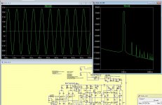
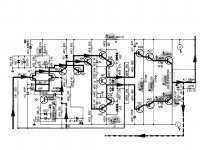
Here it is (from days gone by) the GX -
http://www.diyaudio.com/forums/solid-state/169590-mongrel-supersym-ii-9.html#post2299463
.... I might of added the cascode to
this amp (2 Low Vsat active VAS + 2 high Vceo +2 leds + resistor) this would
really allow for an ideal selection of the "driven" devices.
It "simms" well (below 1+2) , no change in comp. , .0004%THD10k (same).
What DOES change is the FFT (below 1) , less H3/H5 than the original.
Perhaps this attributed to the smooth
(er) sound of the "GX" frugalamp. 🙂
OS
Attachments
Last edited:
Do you considerin to use j-fet input like younger Sansui AX501?
Harder to source. Jfet's "like" a DC servo (added complexity). Using better
BJT's is simple as the 28V 1st stage allows for any device.
BTW , those are proprietary dual devices. 😱
OS
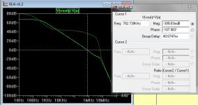
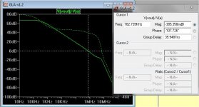
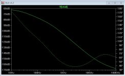
Hawksford bypass vs. standard cascode
Simulated both the hawksford and rail referenced cascodes.
The hawksford (referenced between active VAS emitters and ground) -
it has to be this way.. (oscillation 🙁 ), reduces global loop gain 10db.
This is best for a ultrahigh gain "blameless" enhanced beta style topology (lots of
extra gain "to burn" 😀 )
For the GLA , distortion + PSRR suffers with the hawksford (below 1)
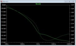
Using the "standard" Cascode, like in my last post , the PSRR is
utterly unbelievable 😱 .... (last attachment) .
OS
Simulated both the hawksford and rail referenced cascodes.
The hawksford (referenced between active VAS emitters and ground) -
it has to be this way.. (oscillation 🙁 ), reduces global loop gain 10db.
This is best for a ultrahigh gain "blameless" enhanced beta style topology (lots of
extra gain "to burn" 😀 )
For the GLA , distortion + PSRR suffers with the hawksford (below 1)
Using the "standard" Cascode, like in my last post , the PSRR is
utterly unbelievable 😱 .... (last attachment) .
OS
Attachments
What ever happened to this thread/project? It seemed like a very nice topology...
Hi,
Yes, what did happen to this thread and project 😕 ? It seems a very interesting project. i would like to build this amp 🙂.
Best regards
rephil
I think OS has moved the activity into his current 'Slewmaster' project. I believe one of the proposed input boards will be based on this design.
Hi,
Yes, what did happen to this thread and project 😕 ? It seems a very interesting project. i would like to build this amp 🙂.
Best regards
rephil
The GLA will be the "symasui input stage board" .. that is next in the
"slewmaster" lineup (new thread -many choices) ... this thread started my EF3 "fetish" ...
OS
Last edited:
- Home
- Amplifiers
- Solid State
- GLA (good little amp) "survivor"