Hello,
just a update on the "Audiophonics Studer900" power supply.
Unfortunately, the workaround of the capacitor that @Jonners suggested did not work for me.
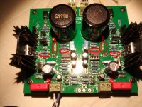
But I found out the issue of my power supply: the positive and negative section of the supply board are not exactly symmetric. There are some resistances that have different values (see picture below).
I have another board that I was using for the 5V supply. That one has the two sections exactly identical. So I used it for the +-15V and the katana started up normally, both positive and negative rail power up immediately.
So I suggest that whoever else has this board to check carefully all components.
P.S. I built a SPICE model (on Tina TI) of this supply in order to see the influence of those resistances and additionally to evaluate its performance.
I will post it on the thread:
low noise Pre-Amp / DAC power supply MJE15034 TL072 Regulator based on STUDER 900
just a update on the "Audiophonics Studer900" power supply.
Unfortunately, the workaround of the capacitor that @Jonners suggested did not work for me.
But I found out the issue of my power supply: the positive and negative section of the supply board are not exactly symmetric. There are some resistances that have different values (see picture below).
I have another board that I was using for the 5V supply. That one has the two sections exactly identical. So I used it for the +-15V and the katana started up normally, both positive and negative rail power up immediately.
So I suggest that whoever else has this board to check carefully all components.
P.S. I built a SPICE model (on Tina TI) of this supply in order to see the influence of those resistances and additionally to evaluate its performance.
I will post it on the thread:
low noise Pre-Amp / DAC power supply MJE15034 TL072 Regulator based on STUDER 900
Attachments
I have another board that I was using for the 5V supply. That one has the two sections exactly identical. So I used it for the +-15V and the katana started up normally, both positive and negative rail power up immediately.
Are you applying power to all three Katana boards at the same time?
I assembled my board myself so I know the two halves are similar, but of course the values could still be wrong!
I will be interested to see what you find.
Last edited:
Are you applying power to all three Katana boards at the same time?
I assembled my board myself so I know the two halves are similar, but of course the values could still be wrong!
I will be interested to see what you find.
Yes, I am powering the entire stack at the same time with +-15V for the opamp board, and +5V for MC and DAC boards. I still get a little sound peak when I pòwer up and power down the stack, but not too much.
I plan to power MC board and DAC board with two separate 5V, but first I want to investigate and fix the resistances on the power supply board (that now I am using for the 5V).
I will keep you posted
Easy enough to ring out ground on the balanced output connections with a DVM, but maybe not such a good idea to use balanced rather than the unbalanced outputs. Usually, the way balanced output are derived from a 6-opamp output stage like the one in Katana means that not all output stage filter processing has been done at that output. Unless the user knows how to finish that, probably better to either use the unbalanced outputs directly, or rebalance them with a two opamp circuit commonly used for that purpose (such as the one shown below).
XLR output is direct from IV stage (with RC filtering). In fact I think that its the same circuit as esssabre used in eval board.
XLR output is direct from IV stage (with RC filtering). In fact I think that its the same circuit as esssabre used in eval board.
True for the old ones, which is not fully filtered. The newer ESS evaluation boards use more opamps that do a little more filtering and buffering for the unbalanced outputs. You can ask them for a copy of ES9038PRO evaluation schematics if you want to see what they are doing now.
PCB (10 units) will be received in about 10 days for testing. I will post updates but on proto (only one unit) , we get noise..we dont get any noise. Its almost at floor of Audio precision machine. Thats about 0.2uV
0 common mode noise, almost no leaking current
Each rail has big capacitor bank , then active filters , then LDOs , then more active filters and finally big caps + supercaps on the output for very low impedance .
@😕cdsgames, where are you with the power supply projects that you are working on? Nirvana (smps) seems to have been problematic for a long time. Is 5v/3A even possible, or could you accept/produce a low noise unit at 5v/1.5A? With the linear supply that you have just embarked upon it appears you are after a dual 5V, 3A &1A unit for the pi and Dac hat. Can you clarify what your goals are and when you expect to deliver on one or both projects?
...
I still get a little sound peak when I pòwer up and power down the stack, but not too much.
...
I will keep you posted
Forgive me for asking what might be a dumb question...
Are you powering up the entire stack up at once?
According to the manual:
Step 3: Power KATANA
Step 4: Power MicroController
Step 5: Power RPI
And then later on:
Power to the OPAMP stage can be switched off when player is idle for extended periods of time
with switch 3 of Micro Controller.
Which to me implies the opamp board should be powered up last, since it can be turned off and on while the rest of the stack is powered on.
XLR output
@CallMeMike, Yes my amp has true balanced XLR inputs and I know the theoretical difference between balanced and unbalanced so I thought the same as you:
Nevertheless, after reading many comments from @Markw4, @cdsgames and others, I’m not sure at all it’s a good idea. Please, correct me if I’m wrong but my understanding is that the XLR outputs on the Katana are missing some filtering compared to the unbalanced RCA outputs, potentially making better SQ by rebalancing the unbalanced output!? The circuit proposed by Markw4 to rebalance seems simple to implement but to connect its output to the XLR connectors on the board, not so sure. Unless the idea is to have the XLR connectors on some external board along with the balancing circuit? Even then, is the proposed rebalancing circuit good enough so it won’t risk to reduce or counterbalance the benefits? I really would like to use balanced XLR but obviously, only if its benefits can be fully exploited.
@cdsgames, You said back in august that XLR output had been tested only with THD board but not with SQ board... Is that still the case?
Thanks to all!
@CallMeMike, Yes my amp has true balanced XLR inputs and I know the theoretical difference between balanced and unbalanced so I thought the same as you:
If you have an XLR input on your amp, it make sense to have XLR all way through...
Nevertheless, after reading many comments from @Markw4, @cdsgames and others, I’m not sure at all it’s a good idea. Please, correct me if I’m wrong but my understanding is that the XLR outputs on the Katana are missing some filtering compared to the unbalanced RCA outputs, potentially making better SQ by rebalancing the unbalanced output!? The circuit proposed by Markw4 to rebalance seems simple to implement but to connect its output to the XLR connectors on the board, not so sure. Unless the idea is to have the XLR connectors on some external board along with the balancing circuit? Even then, is the proposed rebalancing circuit good enough so it won’t risk to reduce or counterbalance the benefits? I really would like to use balanced XLR but obviously, only if its benefits can be fully exploited.
You should take the unbalanced out and run it though a balancing circuit like the one in the schematic below. A dual opamp such as LME49720 can work well for that type of circuit. Don't forget power supply bypass caps.
The most recent thinking on XLR outputs is that they may not be a good idea. Better to take the unbalanced output and re-balance it if balanced is really needed. Sound quality should be better than way.
IV stage goes directly to XLR output (with some filtering). With the new mods that we have on Katana it should not be a problem. Still XLR testing is not completed for SQ it was completed for THD+N
Easy enough to ring out ground on the balanced output connections with a DVM, but maybe not such a good idea to use balanced rather than the unbalanced outputs. Usually, the way balanced output are derived from a 6-opamp output stage like the one in Katana means that not all output stage filter processing has been done at that output. Unless the user knows how to finish that, probably better to either use the unbalanced outputs directly, or rebalance them with a two opamp circuit commonly used for that purpose (such as the one shown below).
XLR output is direct from IV stage (with RC filtering). In fact I think that its the same circuit as esssabre used in eval board.
True for the old ones, which is not fully filtered. The newer ESS evaluation boards use more opamps that do a little more filtering and buffering for the unbalanced outputs. You can ask them for a copy of ES9038PRO evaluation schematics if you want to see what they are doing now.
@cdsgames, You said back in august that XLR output had been tested only with THD board but not with SQ board... Is that still the case?
Thanks to all!
@joshua43214,
It really won't matter when you power the Opamp board IF you use separate +-15V supplies. They can be left on when you power the other rails, they can be off and powered on last. OTOH, IF they are on when you power the other rails AND your Katana is connected to your amp AND it is powered up AND the volume is not all the way down, you will likely get some noise and/or transients as the other rails come up (this is consistent with @fabio1068's comments just above). I don't know how bad the noise and/or transients are, I always put my amp into standby when powering / un-powering the Katana stack. It may be just alarming, it may be amp and/or speaker damaging. I wouldn't recommend trying it.
I believe this is also true if you are using the DC-DC converters to provide the +-15V, but have not tested that.
@Jonathan P & @Markw4, first, the only difference between a THD board and a SQ board is the addition of a filter consisting of 2 resistors and a capacitor on each channel between the output of the DAC board and the input to the Opamp board. Nothing else. So effectively workings of the XLR will not differ between the two, as that all occurs downstream of those filters. Of course, the effects of the filters due to their attenuation will carry through, but the XLR circuitry of the 2 types work the same.
BTW, I posted a schematic that illustrates that filter in post 2574 of the main Allo thread, though I know Allo chose different values for the filter circuit. ALSO NOTE that the feedback filters shown in that illustrative schematic ARE NOT the same as what Allo uses. That is only a schematic to illustrate the input filter used to turn a THD stage into a SQ stage.
ALSO, the output points of the 2 opamp circuits in that schematic are where the Katana balanced outputs are taken, though they add some additional R/C filtering as per @cdsgames comment above.
Also, @cdsgames indicated that the XLR outputs are taken from the I/V stage outputs with additional filtering. @Markw4, I understand you suggest added filtering may be beneficial along with an added stage to produce better balance between the output.
On the filtering, my question to @cdsgames is does the additional filtering on the XLR outputs produce the same level of attenuation (same inflection points and number of poles) as you get through the summing opamp stage that you use to produce the single ended output?
If so, I would expect the XLR output to sound very similar to the single ended output.
One might argue that it might exhibit small differences due to the imbalances that @Markw4 references... and also due to the lack of the additional stage. BUT if the signal goes through the same filtering, just done passively instead of actively, it should function about the same.
Can you clarify this for us, @cdsgames?
On using the balanced output versus the single-ended output of the Katana, that is something I have on my list of things to try, but it is not a high priority as now. BUT I suggest as long as the filtering at the connection is the same or at least very similar between the single-ended and balanced outputs, there should be no problem using the balanced outputs from the Katana. AND doing what you suggested, @Markw$, would take a significant redesign of the Opamp board AND may be difficult to fit in the existing board space, as those Sparkos Lab discrete opamps take up a lot of board real estate.
I hope this clarifies.
Greg in Mississippi
Last edited:
Regarding balanced outputs, even after filtering there is still a matter of un-removed common-mode distortion and noise on the balanced outputs. John Siau, designer of the Stereophile A+ recommended and SOA-rated Benchmark DAC-3 makes the same points I do in an interview at ASR. I came to my own opinions prior to finding out about the the interview, but we both appear to agree that ESS does it the wrong way. The balanced outputs should be all cleaned up before going into the users equipment. The user shouldn't be relied upon to make sure their equipment finishes what should have been finished inside the dac.
However, anyone can do as they please, of course. Using ESS-style balanced outputs some people may not notice any adverse consequences to sound quality and others might. Only way to find out though would be to try it both ways and compare. Most people would probably not bother, and would just take their chances instead. Your choice. I prefer good sound quality myself and am not lazy about doing things properly.
However, anyone can do as they please, of course. Using ESS-style balanced outputs some people may not notice any adverse consequences to sound quality and others might. Only way to find out though would be to try it both ways and compare. Most people would probably not bother, and would just take their chances instead. Your choice. I prefer good sound quality myself and am not lazy about doing things properly.
@Markw4, If I hear you correctly, you think that not only rebalancing the unbalanced (RCA) output should sound better than using the XLR output on the Katana, due to lack of filtering on the balanced (XLR) output path, but you also think that no matter what, the end result would never be as good as if the work would have been done within the ESS ES9038Q2M chip? If that's the case, I would be tempted to conclude that it's definitely not worth trying to use the balanced output or to rebalance the unbalanced output. Nevertheless, I'm still kind of skeptical about that conclusion of mine when I see some high quality, very expensive products, offering balanced XLR output using the same DAC chip.
Here's one example:
https://www.ayre.com/products/amplification/ex-8/
So unless I misunderstood what you meant... It sounds to me like either Ayre has put a lot of effort doing the job on their own (externally), or the chip is able to do it but allo didn't take advantage, or some other reason I can't think of?
Thanks for sharing your valuable input!
The problem is not that balanced outputs cannot be properly implemented, they can be. It's just the ESS took a shortcut on their evaluation boards making some designers think that was a good reference design, not an evaluation test bed for engineers. Engineers should know if they take the unbalanced outputs from the ESS reference board that the processing is not finished, would be the view of ESS.
I saw one guy on diyaudio selling Sabre dacs with PRO chips and lecturing buyers they need to fix their power amps that didn't work properly with the ESS evaluation type unbalanced outputs. He acted like such customers where stupid for not having power amps that were designed to finish the job. I think ESS just assumed that designers would know what kind of balanced circuits exist in different kinds of audio products and design their balanced outputs knowing if they would work in a particular application. On the other hand, many designers seemed to take the ESS evaluation board design as ESS saying their balanced outputs should work with any equipment. That is not that case, of course. Designers who are very familiar with all sorts of audio equipment designs would know that. Designers who assumed ESS was advising them that the evaluation circuit should always work fine were under a misunderstanding. At least, that's my take on it. IME, ESS does not do a very good job supporting its customers, the dac designers out there. ESS assumes they will have to figure out everything for themselves, but designers often assume it is like the old days when manufacturers provided very good support to designers. Not anymore, things have changed. Same basic issue with AKM, figure it all out yourself seems to be what they expect designers to do, too.
I saw one guy on diyaudio selling Sabre dacs with PRO chips and lecturing buyers they need to fix their power amps that didn't work properly with the ESS evaluation type unbalanced outputs. He acted like such customers where stupid for not having power amps that were designed to finish the job. I think ESS just assumed that designers would know what kind of balanced circuits exist in different kinds of audio products and design their balanced outputs knowing if they would work in a particular application. On the other hand, many designers seemed to take the ESS evaluation board design as ESS saying their balanced outputs should work with any equipment. That is not that case, of course. Designers who are very familiar with all sorts of audio equipment designs would know that. Designers who assumed ESS was advising them that the evaluation circuit should always work fine were under a misunderstanding. At least, that's my take on it. IME, ESS does not do a very good job supporting its customers, the dac designers out there. ESS assumes they will have to figure out everything for themselves, but designers often assume it is like the old days when manufacturers provided very good support to designers. Not anymore, things have changed. Same basic issue with AKM, figure it all out yourself seems to be what they expect designers to do, too.
Last edited:
@Markw4, I'm definitely not as knowledgeable as you are and I'm not sure if the 'evaluation boards' you mention would be different than actual boards sold to customers, so I apologize in advance if I get it all wrong. What I understand is that the unbalanced output on the Katana or maybe on any DAC using ESS chip might sound better than the balanced output? If so, do you think it would/could also be the case using the simple circuit you suggested in previous posts to balance the unbalanced output? In other words, we'd better stick with unbalanced RCA output on the Katana unless we can make a high quality design to compensate for what ESS (allegedly) assumed consumers would do themselves, like Ayre apparently managed to do?
Evaluation boards are intended for sale to engineers, not to end users. They are to assist with engineering test and evaluation of a device being considered for use in an end-use design.
I don't know how Ayre implemented their balanced outputs. If they used the circuit I recommended, then that should work fine. There is no reason not to use that circuit if it is constructed and powered properly. It is used in many pieces of professional audio equipment. If you need balanced outputs for some reason, that is how I would recommend to make them. I would not recommend to use the ESS evaluation board balanced output circuit. (Of course, professional engineers or others who know quite well what they are doing should make their own calls.) All the foregoing IMHO only, of course.
I don't know how Ayre implemented their balanced outputs. If they used the circuit I recommended, then that should work fine. There is no reason not to use that circuit if it is constructed and powered properly. It is used in many pieces of professional audio equipment. If you need balanced outputs for some reason, that is how I would recommend to make them. I would not recommend to use the ESS evaluation board balanced output circuit. (Of course, professional engineers or others who know quite well what they are doing should make their own calls.) All the foregoing IMHO only, of course.
Last edited:
@Markw4, I don't necessarily "need" balanced outputs but since my AMP offers truly balanced XLR inputs, I feel that it might be smart to take advantage from it if I feel confident that I can get good quality, truly balanced outputs from the Katana.
Now, on "professional engineers or others who know quite well what they are doing should make their own calls", I'm definitely more on the software side than on the hardware side but I'll trust you on that and have a closer look into the balancing circuit.
I guess the idea would be to implement this circuit and the XLR connectors on an external PCB? Would you connect it right where the RCA are connected?
XLR , there is filtering on the IV stage and filtering after , from what I remember its the same poles like summing .
I have a few people and tried XLR and report excellent sound.
Compared with unbalanced Katana I would expect the same sound quality or even a bit better.
I have a few people and tried XLR and report excellent sound.
Compared with unbalanced Katana I would expect the same sound quality or even a bit better.
@😕cdsgames, where are you with the power supply projects that you are working on? Nirvana (smps) seems to have been problematic for a long time. Is 5v/3A even possible, or could you accept/produce a low noise unit at 5v/1.5A? With the linear supply that you have just embarked upon it appears you are after a dual 5V, 3A &1A unit for the pi and Dac hat. Can you clarify what your goals are and when you expect to deliver on one or both projects?
Hi , I wont comment until the new PCB arrived in the office. LPS , I should have some update by next week (new PCB in on the way). Nirvana... at 1.5A its already very low, but I am waiting for new PCB (next week) and I will update a week after. I am confident with LPS , Nirvana we need testing .
Hi , I wont comment until the new PCB arrived in the office. LPS , I should have some update by next week (new PCB in on the way). Nirvana... at 1.5A its already very low, but I am waiting for new PCB (next week) and I will update a week after. I am confident with LPS , Nirvana we need testing .
I hope you are successful with Nirvana, the iFi 5V is OK if you apply the grounding modification ($13 for the iec to spade connector from iFi), however the voltage needs to be 5.1~5.2V to avoid under voltage warnings on the pi (and thats a 3B not the new B+). The dual linear psu would be a good solution for pi +dac and I'm sure that can be produced. ~$150 if you can get there for the linear is a fair price for a high quality low noise supply with published specs, and will be good enough for the vast majority of buyers.
Well I finally pulled the RPi 3B+ from under my Allo Digione and put it under the Katana.
Power to the MCU is from an iFi 5V PS, and the isolator is powered from an LG phone charger.
Have to say it sounds pretty decent so far. A bit lacking in bass, and some distortion in the upper vocals. I expect that will settle down alot once it is burned in. Staging is better than I expected so far. Certainly plenty good enough to listen to some music while I finish putting the power supplies and chassis together. The boards are all assembled, the only thing I am waiting on is hook up wire.
One thing I have not heard discussed so far in this thread is volume control. My build will also have a Mesmerize B1 buffer incorporated into it, so I will be able to do some A/B listening between a nice DC coupled "pre-amp" (gain of 1...), and the built in software volume control. I expect a substantial improvement in quality using external attenuation. The manual for the Allo Digione states that using the software volume control degrades quality, I expect the same will be true for the Katana.
-Josh
- Home
- Source & Line
- PC Based
- Getting the best out of Allo.com's new Katana DAC...