No, 10kc. Makes you feel old.
With some faster drivers, such fat slow parts can "do audio", testing at the 1W level at the top of the audio band. Since real speech/music falls-off past 1kHz/kc, this is rational. (We used to be warned to NOT try full power at high frequency because the shoot-through current would melt the transistors.)
For me: „learning by reading“
For all others, this equals to „learning by babbling“ [emoji1787] (this is pointed at me, and I have no idea what kc is—kC, kilo-Coulomb? )
Thanks PRR
Last edited:
Germanium transistors E Databook download link:
https://www.rsp-italy.it/Electronic...ransistor Characteristics Tabulation 1962.pdf
Source: Electronics Books
 Electronics Databooks
https://www.rsp-italy.it/Electronic...ransistor Characteristics Tabulation 1962.pdf
Source: Electronics Books
Electronics DatabooksAttachments
KiloCycles
Old Yank for KHz
As much Brit as Yank. The crossover was like 1968, but kc actually lingered longer in British than American (without accounting for actual popularity, just use-frequency).
Google Ngram graph
Maybe it is as good as the sony VFET?
Many Ge transistors data sheet parameters are worse than ordinary IRF***mosfets or modern Si bipolars.
On the other side Ge semiconductor have different characteristic compared to silicon material structure.
In audio hobby, entertainment try something new or rediscovering old tech with modernised topologys is interesting.
Without any garanties of audio quality or personal satisfaction
....it's investigation 🙂
hi all, its been a while since I did anything with germanium, so I revisited single ended classA headphone amp with germanium transistor idea
while back I posted some links to aliexpress, where someone was selling such headphone amp
no schematics, so I had to improvise myself
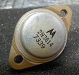
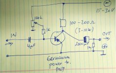
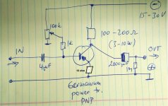
I got four of PNP germanium output transistors, 2N3614, and Soundhappy posted datasheets, they are new never used, measure good, so I put together this simple circuit
just tested it, it works, sounds decent, plenty of power for headphones, and it even drives small fullrange speakers
any comments on the schematics?, its as simple as it gets, I would like to squeeze as much quality sound as possible, not after power
I will do series of simple distortion and fr response measurements once I have time
cheers!
while back I posted some links to aliexpress, where someone was selling such headphone amp
no schematics, so I had to improvise myself
I got four of PNP germanium output transistors, 2N3614, and Soundhappy posted datasheets, they are new never used, measure good, so I put together this simple circuit
just tested it, it works, sounds decent, plenty of power for headphones, and it even drives small fullrange speakers
any comments on the schematics?, its as simple as it gets, I would like to squeeze as much quality sound as possible, not after power
I will do series of simple distortion and fr response measurements once I have time
cheers!
Attachments
It is not immediately obvious from your schematic at what current you run the transistor. 75mA? If you do pass real current the lack of any temp compensation will let itself known.
Yes, the current...completely selectable at this point. Current for now depends on power supply and the trimmer settings. I am feeding it from regulated power supply, so I can decide.
I set the trimmer just by listening on headphones to minimum obvious distortion. But I have not done any real distortion tests.
I do have small heatsinks on transistors, and they are not even warm. Resistors do get warm, but not hot.
Last time I checked, it was ~45 mA.
I set the trimmer just by listening on headphones to minimum obvious distortion. But I have not done any real distortion tests.
I do have small heatsinks on transistors, and they are not even warm. Resistors do get warm, but not hot.
Last time I checked, it was ~45 mA.
I will test distortion with and without 10 ohm emitter resistor...
Soundhappy, since the transistors I am using are 85watts, 7A, and I am running them ~50mA, I may not need the thermistor...
Soundhappy, since the transistors I am using are 85watts, 7A, and I am running them ~50mA, I may not need the thermistor...

ok folks, here we go, you may not like the results, but it is what it is
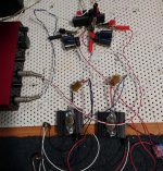
pictured is set up, really just two transistors, small heatsinks, few resistors, two caps
I did four measurements, all at -10dB of the sound card, quite loud for headphones, so with 30ohm load
high level, high distortion
pictured is set up, really just two transistors, small heatsinks, few resistors, two caps
I did four measurements, all at -10dB of the sound card, quite loud for headphones, so with 30ohm load
high level, high distortion
Attachments
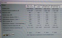
shown are four measurements, two without emitter resistor, and two with (second two labeled feed)
two are at lower power supply (12-13volts) and two at higher power supply (18-20 volts).
lower power leads to higher distortion, more volts, lower distortion...makes sense, since the current is bigger
however, emitter resistor (2R2) has more dramatic effect, so perhaps I should double it
I adjusted the trimmers for highest signal on the output, which I believe may be lowest distortion too, but not sure
at lower power supply, no feedback, distortion at -10dB was 2.97%. Yes, that high. At 17V power supply, it dropped to 2.45%
however, with emitter resistor, distortion dropped to 0.98% at lower volts, and 0.495% at higher volts
spectrum is purely second harmonic, pleasant, at normal headphones listening
I have some 120hz hum signal to take care of, since I did not use regulated power supply right now
fr response rolls on both ends, I would understand lower fr by not enough capacitance on the output/input, but I am not sure why it rolls of at higher frequencies
I would like to fix this
any idea? btw it rolls less with emitter resistor, so making it bigger should address this as well as distortion
cheers!
Attachments
The collector resistor must be equal to or less than the load.
A follower can be built if a load resistor is included in the emitter.
A follower can be built if a load resistor is included in the emitter.
The collector resistor must be equal to or less than the load...
Maximum efficiency calls for DC load to be 1.4 times the AC load; and about 70% of supply voltage dropped across it.
Maximum efficiency will not be much over 5%. (Most books get this wrong.)
Distortion at *maximum* output is always 26% mostly 2nd. NFB can reduce this.
Yes, a follower will tend to be lower THD. As a follower, near 1%.
To get low THD you can build it MUCH bigger than you need. Build for 1Watt, run at 10mW output, THD may be 2.6%.
The proposed one-transistor plan may also be distorting at the input due to low nonlinear input impedance loading the source.
You really want a gain and buffer stage. If your religion allows it.
- Home
- Amplifiers
- Pass Labs
- Germanium investigations