What about to use audio grade GE transistors ?Once the heatsinks arrive I will do a better analysis.
https://www.diyaudio.com/community/threads/germanium-investigations.348948/post-6216162
Because the 1t806 was readily available until a few months ago and the datasheet says it can be used for amplifiers. https://ldsound.club/index.php?threads/1t806a-1t806b-1t806v-gt806a-gt806b-gt806v-gt806g-gt806d.865/

1T806 (GT806) - work well in amplifiers. I built a lot of amplifiers on them, as well as on 1T813.Because the 1t806 was readily available until a few months ago and the datasheet says it can be used for amplifiers.
You just need to pick them up well in pairs according to the gain.
Germanium circuits typically require lower input, they were often designed in the era when turntables and mics were the only input devices.You didn't even get as far as my second paragraph. I know the transistors need heatsinks but don't have them yet. With the link jpatay provided I now know that this amplifier is only rated for 5-6 watts and it was into clipping. Reducing the input to 0.7v reduces the distortion to 0.2%. Once the heatsinks arrive I will do a better analysis.
I have built many amplifiers, but what I like the most is the sound of the germanium transistor amplifiers. I especially like how low frequencies sound. The bass is rich and full. 👍
Do you have a Ge Amp schematic to share?I have built many amplifiers, but what I like the most is the sound of the germanium transistor amplifiers. I especially like how low frequencies sound. The bass is rich and full. 👍
1T806 (GT806) - work well in amplifiers. I built a lot of amplifiers on them, as well as on 1T813.
You just need to pick them up well in pairs according to the gain.
You're right about gain as these devices vary wildly and don't seem to age well. I bought 3 batches of 10 from different sellers. Each batch has 1-2 that are outright dead or have a gain of 1. The rest in the teens and a few higher with 30-40, so your typical bathtub curve.
This was my method of testing hfe. https://www.diystompboxes.com/smfforum/index.php?topic=102014.msg910364#msg910364
I settled on this pattern. The sound is great.Do you have a Ge Amp schematic to share?
http://devicemusic.ucoz.ru/forum/6-347-1
But building such an amplifier would be difficult. It is necessary to have a lot of GT402 / GT404 transistors and it is also difficult to mount them on the heat sink.
Here is a similar circuit and more powerful on GT703 / GT705 transistors. It also sounds great.
http://devicemusic.ucoz.ru/forum/5-335-1
Germanium transistors made in the USSR have a lot of defects. Therefore, in order to select them in pairs, you will have to purchase a lot of them. 😉This was my method of testing hfe.
Ok, as is this design is good for 5 watts or so before the peaks start rounding and distortion goes up. However offset is the real killer here. When power is first applied and everything is cold the offset is -1v and as the heatsinks warm up it swings to over +1v. Some serious temperature compensation is needed.
Attachments
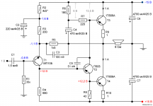
It is better to transfer the circuit to unipolar power, then the speaker will be safe. The author advises the middle terminal of the transformer not to be connected to the "ground", but this must be checked. Then, too, a constant voltage on the speaker will not crawl.Ok, as is this design is good for 5 watts or so before the peaks start rounding and distortion goes up. However offset is the real killer here. When power is first applied and everything is cold the offset is -1v and as the heatsinks warm up it swings to over +1v. Some serious temperature compensation is needed.
https://www.salonav.com/arch/2021/06/klassicheskaya-sxema-jlh-na-germanii.htm
The author also advises replacing the VT1 transistor with a silicon BC556. Then the current will be more stable. This will not affect the sound. The current can be set to 0.8A.
Last edited:
Have a dozen NOS Texas Instruments' 2N1305 that I acquired from my grandfather. They are the steel cased type. He was a TV repairman and a tinkerer. Not sure how useful they are but I'd love to see someone use them rather than just trash 'em. So, someone can have them for the cost of postage. Let me know and they're yours.
I may have more or others in a bin somewhere, I'll have to look.
Please, in lower 48 only. 🙁
I may have more or others in a bin somewhere, I'll have to look.
Please, in lower 48 only. 🙁
The author wrote: "The middle point of the secondary winding of the transformer can be connected to the signal midpoint, but it is safer for the speaker not to connect them".
The result is a circuit with a bipolar power supply with a floating "ground" (to protect the speakers from DC in case of an accident).
The result is a circuit with a bipolar power supply with a floating "ground" (to protect the speakers from DC in case of an accident).
Last edited:
The author wrote: "The middle point of the secondary winding of the transformer can be connected to the signal midpoint, but it is safer for the speaker not to connect them".
The result is a circuit with a bipolar power supply with a floating "ground" (to protect the speakers from DC in case of an accident).
Is this what the author is talking about?
Part of me really wants to do something crazy like a thermistor feeding a microcontroller to keep the bias stable. 😛
Attachments
Yes.Is this what the author is talking about?
If you want, you can try, but even so the amplifier will work well. On П605 (П609) you also need to install a heat sink.Part of me really wants to do something crazy like a thermistor feeding a microcontroller to keep the bias stable. 😛
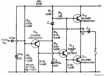
This was probably answered once before but my mind is drawing a blank. R3 is specified as k68. What value is that supposed to be? Surely it can't be 68k so maybe 6.8k? But that doesn't make sense either. R9 is 43 ohms so it can't be 68 ohms then 🤔
Yes, R3 - 680 Ohm, R9 - 43 Ohm.This was probably answered once before but my mind is drawing a blank. R3 is specified as k68. What value is that supposed to be? Surely it can't be 68k so maybe 6.8k? But that doesn't make sense either. R9 is 43 ohms so it can't be 68 ohms then 🤔
Are you building an amplifier with a single 30V power supply? It is necessary to reduce the supply voltage to 24 V. You can use a switching power supply. When establishing amplifier modes, it is necessary to install an incandescent lamp 24 V / 21 W or a powerful resistor 24 .... 30 Ohm instead of a fuse.
I'm not building anything permanent yet, it's all just prototyped on my bench. Before this my projects were always tube based so this seemed like a good excuse to understand the details of how transistor amps were designed. Now it's pretty clear why everything was capacitor coupled and class B back then.
A small germanium based amp seems like a unique addition for the collection.
A small germanium based amp seems like a unique addition for the collection.
- Home
- Amplifiers
- Pass Labs
- Germanium investigations