I checked out your circuit in detail, and agree almost totally with your transistor choices.
I know you are using JFETs for the current sources.
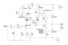
But in keeping with the original circuit, KSA992 / TTA004B are equally good in those positions.
Of course 2SA970BL is arguably even better, but is unobtanium.
2SC2682 and 2SC1941 are also obsolete.
But TTC004B is very close to 2SC3423 and is an active part.
Comparing 2SC3284 to MJL3281 (or 2SC3281 ?), the latter is more linear in hfe vs Ic.
I also like Sanken devices, but it seems to be more difficult to find than the On Semi.
They will all fit my Gerbers.
One needs to add 4.7p in parallel with the feedback resistor (R7 in the schematics in post #1).
Have not tried them all in the JLH circuit like you did, so only my armchair commentary.
And many thanks for sharing with us.
Patrick
I know you are using JFETs for the current sources.
But in keeping with the original circuit, KSA992 / TTA004B are equally good in those positions.
Of course 2SA970BL is arguably even better, but is unobtanium.
2SC2682 and 2SC1941 are also obsolete.
But TTC004B is very close to 2SC3423 and is an active part.
Comparing 2SC3284 to MJL3281 (or 2SC3281 ?), the latter is more linear in hfe vs Ic.
I also like Sanken devices, but it seems to be more difficult to find than the On Semi.
They will all fit my Gerbers.
One needs to add 4.7p in parallel with the feedback resistor (R7 in the schematics in post #1).
Have not tried them all in the JLH circuit like you did, so only my armchair commentary.
And many thanks for sharing with us.
Patrick
Thanks, Patrick
I spent months testing the transistor because it is obvious that such a simple amplifier will be sensitive to the choice of parts, especially the driver / VAS transistor which has a lot of impact on the overall sound.
An SMD 2SA1312 can be placed for the input transistor, Mouser has them in stock. Mouser has some other interesting transistors besides the TTC004 that I have yet to try, unfortunately mostly SMD.
Compensation with 4.7pF is only needed with 2SC1941, with all other transistors not required.
I use 2SA1312 a hell of a lot. I have hundreds.
But they cannot take so much power, so limited to low bias (<4mA).
Have you tried TTC3710 ?
High capacitance, which does not have to be a disadvantage in some circuits.
But linear to much higher current.
Also interesting I find 2SC2873.
Do let us know if you have more results. 😉
Patrick
But they cannot take so much power, so limited to low bias (<4mA).
Have you tried TTC3710 ?
High capacitance, which does not have to be a disadvantage in some circuits.
But linear to much higher current.
Also interesting I find 2SC2873.
Do let us know if you have more results. 😉
Patrick
Hi Folks
just to add my thanks to Geoff Moss for his mods to the JLH (and ESP for hosting the site), and just to add that you can add more MJ15003's to the output stage if you are so inclined and have the heat sinking and power supply. I have a version with 4 output pairs that gives a healthy 80 watts into 8 Ohms with THD below 0.1. At powers below 10 watts, the THD is way down into the noise.
Gets a bit warm though: the heat sinks get up to a stable 45C after 30 minutes or so 🙂
Cheers
Mike
So I replaced the BJT current sources with Spice ideal current source.
Distortion does not change.
One can conclude that the current source is currently not deciding factor.
Cheers,
Patrick
Distortion does not change.
One can conclude that the current source is currently not deciding factor.
Cheers,
Patrick
Here's one I prepared earlier. 🙂 - I have just put the data into Excel as I tend to visualise it that way
This is the distortion vs power profile for the actually built 4-pair. There are a couple of 'erroneous' readings at the bottom end as this is getting on towards the measurement limitation. Note the log scale on the distortion axis. Iq was just over 4 Amps and the measurement frequency was 996 Hz.
As one would expect, 2nd harmonic dominates. 4th harmonics and above are very, very low until the amp starts to clip at about 90 Watts output.
The portion from about 30 to 80 Watts is interesting: I think this probably due to the various Hfe values of the pairs interacting. Nevertheless, it acts and sounds very good.
Happy listening
Mike
Attachments
Last edited:
Spice simulations depends on the model being used.
Different models will produce different results even with the same circuit.
And of course none of those compares to real measurements.
Cheers,
Patrick
Different models will produce different results even with the same circuit.
And of course none of those compares to real measurements.
Cheers,
Patrick
And finally the Gerbers in zip files.
As stated above I have double checked but cannot guarantee 100% free of error.
Patrick
.
Hi, what are the values of C3A and C3B for the power supply ?
Richard
I am definitely a novice 🙂 Reference to the quiescent current doesn't mean much to me unfortunately.
#35 There is sound, or there is no sound, a class A amplifier consumes 4 times more power than it can give at the output
Heavy, hot, expensive ....
Heavy, hot, expensive ....
Tim de Paravicini says this does not apply to his design for the MF A1, which is 50% efficient.a class A amplifier consumes 4 times more power than it can give at the output
Class A has a theoretical efficiency of up to 50%. In practice, less. It is necessary to take into account the losses in the power source (transformer, rectifier, stabilizer, etc.).
A single-ended circuit with a resistor can be less than 10% efficient (Houston, Nelson Pass).
An amplifier topology like JLH2005 does not exclude the possibility of working in class AB when using darlington or mosfet.
A single-ended circuit with a resistor can be less than 10% efficient (Houston, Nelson Pass).
An amplifier topology like JLH2005 does not exclude the possibility of working in class AB when using darlington or mosfet.
Hi again Folks,
for what its worth. The efficiency of high power JLH that I mentioned (with 4 output pairs) is:
Power in = (2 X 37.5 (+/- VCC) x 4 Amps(Iq)) = 300 watts
Power out = 85 Watts
efficiency is approx 35.3%
Mike
for what its worth. The efficiency of high power JLH that I mentioned (with 4 output pairs) is:
Power in = (2 X 37.5 (+/- VCC) x 4 Amps(Iq)) = 300 watts
Power out = 85 Watts
efficiency is approx 35.3%
Mike
- Home
- Amplifiers
- Solid State
- Geoff Moss's JLH-2005 design files