Then I have a dilemma, I can’t afford to get it repaired without selling off another amp , either my Croft phono integrated or my equally rare Myst tma3, or bin the Restek 😞
Unplug the unit from AC power. Connect DVM leads to the AC plug prongs of the power cord going into the amplifier. With the power switch off, do you measure any resistance? With the power switch on do you measure any resistance that way? If there is a fuse open in the primary of a transformer then IME it will measure as 'open circuit' with an ohm meter. If there are two transformers in parallel then you may need to disconnect one transformer primary so that you are only measuring the resistance of one transformer at a time. If there is a relay that turns on power to the transformers then you may have to check resistance after the relay. If you don't know or aren't sure you know how to do any of that safely then don't try it.
Regarding checking transistors, you DVM appears to have a diode symbol at the rotary switch position for measuring resistance. Read the DVM manual for instructions on how to get it into diode check mode. See if it says anything about how to check bipolar transistor junctions. If not, maybe we can find instructions for you at some website or youtube video.
Regarding checking transistors, you DVM appears to have a diode symbol at the rotary switch position for measuring resistance. Read the DVM manual for instructions on how to get it into diode check mode. See if it says anything about how to check bipolar transistor junctions. If not, maybe we can find instructions for you at some website or youtube video.
Last edited:

Yes I have a schematic, but I’m not sure if I’m allowed to share it on an open forum
The multimeter reads nothing when i connect it to the power in prongs neither with the power button on or off .
measuring the potentially faulty transistor I get a reading of 036.3 , the identical transistor on the opposite channel reads 056.5Unplug the unit from AC power. Connect DVM leads to the AC plug prongs of the power cord going into the amplifier. With the power switch off, do you measure any resistance? With the power switch on do you measure any resistance that way? If there is a fuse open in the primary of a transformer then IME it will measure as 'open circuit' with an ohm meter. If there are two transformers in parallel then you may need to disconnect one transformer primary so that you are only measuring the resistance of one transformer at a time. If there is a relay that turns on power to the transformers then you may have to check resistance after the relay. If you don't know or aren't sure you know how to do any of that safely then don't try it.
Regarding checking transistors, you DVM appears to have a diode symbol at the rotary switch position for measuring resistance. Read the DVM manual for instructions on how to get it into diode check mode. See if it says anything about how to check bipolar transistor junctions. If not, maybe we can find instructions for you at some website or youtube video.
The multimeter reads nothing when i connect it to the power in prongs neither with the power button on or off .
In diode check mode you are not measuring resistance, instead you are measuring volts. Numbers like 36.3 sounds more like ohms than volts. You may have to move the rotary switch to the resistance position then push a button to set the meter into diode check mode. Did you read the manual? A forward biased PN junction typically measures around somewhere around 0.6v. If you reverse the leads then the junction should be reversed biased and the voltage should read something like OL (over load). However, if there are any resistors or other circuitry attached to the transistor then you may be measuring the voltage drop across that circuitry. In that case you might need to disconnect the transistor leads so that there is nothing to measure but the transistor itself.
I have the tester in diode mode and the transistor is giving a reading of 056.1 or 000.1 when I swap the + and -
Yes I have a schematicI surmise there is no complete schematic available?
Do you confirm that the diode check mode indicator as shown below in the orange box is lit?I have the tester in diode mode and the transistor is giving a reading of 056.1 or 000.1 when I swap the + and -
If so, and if the transistor is disconnected from other circuitry then it is bad.
Yes I have it on the correct setting, the transistor is still connected on the board .
Would the transistor stop the amp powering up then ? Would that stop the click from the relay?
Would the transistor stop the amp powering up then ? Would that stop the click from the relay?
The 220 uF capacitor you point to in Post 26 is a bypass capacitor. If all it did was short to chassis you could be in luck. You may in that case be looking at a blown rectifier (maybe) or maybe just a blown fuse. But if that pin bent and touched some other node in the circuit you could be in for a lengthy repair. Are there any indication or burn marks where the capacitor pin connected?
Is there any way to separate the power supply from the rest of the amp so you can test that separately?
Tom
Is there any way to separate the power supply from the rest of the amp so you can test that separately?
Tom
In that case the transistor is still connected to other circuitry so the meter reading may be invalid.Yes I have it on the correct setting, the transistor is still connected on the board.
If the transistor is still connected to the rest of the board you will be measuring the transistor plus everything that it is connected to. Not just the transistor. Is that what you want?Yes I have it on the correct setting, the transistor is still connected on the board .
Tom
Hi Tom , if I knew how to test the power supply I would do so mate .
The only burn evidence is around the capacitor negative pin which btw when soldering it doesn’t flow or anything

The only burn evidence is around the capacitor negative pin which btw when soldering it doesn’t flow or anything
I can't make sense of that picture. In part because it's pretty out of focus. But the burn mark is obvious. It looks to me like the arc was at the fat trace leading to the 3-terminal device at the edge of the board. I'm guessing that 3-terminal device is one of the output devices.
Go pull out the schematic and mark/highlight on it the node where the burn mark is.
Does this amp have any sort of over-current protection? Does it protect against over-current in all the output devices or it it just hooked to one device?
Tom
Go pull out the schematic and mark/highlight on it the node where the burn mark is.
Does this amp have any sort of over-current protection? Does it protect against over-current in all the output devices or it it just hooked to one device?
Tom
I can make sense of it. That was a collector-emitter short. The fat traces are the clue. It wouldn‘t have destroyed that transistor immediately, but would have taken out the complement on the other side. Driver as well as output. The C2344/A1011 driver pair was nice (really nice) but comparatively fragile so look for blown drivers. Once the other transistor died it may take out the one that was originally shorted. Likely it was confined to the output stage, the worst that would happen is blowing all 4 outputs, both drivers, and maybe the Vbe multiplier. Any emitter or base resistor needs to be checked too. They can open up and still look perfectly normal.
I can't make sense of that picture. In part because it's pretty out of focus. But the burn mark is obvious. It looks to me like the arc was at the fat trace leading to the 3-terminal device at the edge of the board. I'm guessing that 3-terminal device is one of the output devices.
Go pull out the schematic and mark/highlight on it the node where the burn mark is.
Does this amp have any sort of over-current protection? Does it protect against over-current in all the output devices or it it just hooked to one device?
Tom
Attachments
Guys I think I’m way out of my league here and thinking i perhaps should just can’t my loses and move on .
Sure. You can give up if you wish. Or you can accept the learning opportunity.
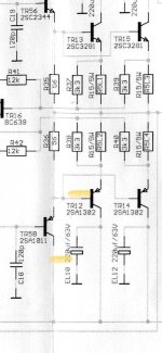
So you've kinda-sorta marked the base connection to TR12. Are you sure it's the base pin that got shorted to the cap? Is the back of the transistor up against the red object in the picture in Post 53? If so, I think it's the emitter pin that got shorted to ground.
I would start by removing TR12 and TR13. Then see if the amp can power up without acting up. If it still acts up, remove TR14 and TR15.
With the transistors out of the circuit you should be able to verify the emitter resistors. They're all 0.15 Ω. Your meter will read high. If you short the probes together you'll probably see 0.2 Ω or so, so keep this in mind when you measure the emitter resistors (R5L1 - R5L4). If they read much beyond 0.5 Ω they're probably toast.
You can also check the transistors using the diode setting on your meter. With one probe on the base of the transistor you should see a diode to the collector and another diode to the emitter. If you reverse the probes you should see an open circuit. The PNP devices will show the diodes in the opposite polarity as the NPN devices. Measuring from collector to emitter should show an open circuit in both directions.
With the output stage removed, the amp should be able to power up without acting up. It should have a reasonably low DC offset on the output. I'd expect <100 mV. If not, the drivers are likely shot. So pull those (TR56, TR58). Check them with the meter.
TR16 detects over-current. It's possible that it's dead as well. In fact, if the amp powers up with the output stage removed, has low DC offset on its output (so on the 'inside' of the output inductor), but the output relay still clicks, I bet TR16 is done.
... or you can give up.
Tom
Thanks Tom , you have given me options that I understand and can act on , most appreciated, I will let you know how it goes. It will take time as there is no way to access the underside of the board without removing it .
The negative pin of the capacitor was touching the wide solder strip in the picture NOT the wide solder strip near that red band/cable .

- Home
- Amplifiers
- Solid State
- Gents I’ve screwed up big time