Unfortunatley it's complexity and small quantiy of build means not many ( any?) are familiar with it from a service point of view. Even it's parents don't want to know it as you've seen. It's (overly) complex design with micrcontroller interface make it a nighmare to trouble shoot.- even the best and most helpfull techs from the DIY site are being helpfull, but staying away from actually working oin it. This is a case where some may offer, but not have the experience and most of those with the experience know better than to try. You have a nice chassis and power supply - while it's not likley what you want to hear you should consider put something else in the chassis - despite the legend of the original's audio peformance -? 
ticknpop... I think you're right. Everyone says it's not that complicated and can be repaired but no one seems to be stepping forward to actually offer to repair it.
What do I have to do... beg?! I am willing! 😉
I'm ready to ship it anywhere in the USA. I have one stealth amp packed on a pallet now. All I have to do is call a freight company to come pick it up.
I don't really want to rip the guts out of the chassis and have someone build an amp in it. That would be like taking the engine out of a ferrari and sticking a modded VW bug engine back in. Not a completely bad thing but still... it's not a ferrari anymore.
What would the ferrari be worth without it's original engine?
Mmm, what would an original with a totally trashed V12 be worth ?
(Zero, if it's a 400i or 412i)
The 1989 Italian Humvee contender with a German AMG engine transplant of near 70 year old Queen of Rockin Rolla was intended to fetch $250K on the collector market.
It can be yours for $150k, still 50% above current average value.
Your amps look very impressive, but also a classic example of zealous over-engineering.
You might consider to keep the original Stealth engines intact, but rip out the fancy central door-lock system and power windows.
Easier to repair, and much more reliable.
Attachments
Hmmmm, maybe I should go that route. I've obviously got nowhere in the last 5 years trying to get them repaired as they are.
Would someone here be more interested in re-building the amp/s using some of its components and tossing others?
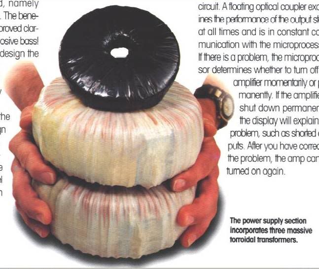
What would you suggest be done to the amp exactly? I assume the massive torroidal transformers would be reused.
Would it be easier or more difficult to make an amp into a monoblock? I do have 3 of the amps. It would be cool having 2 of them made into monoblocks! 😎
Would someone here be more interested in re-building the amp/s using some of its components and tossing others?
What would you suggest be done to the amp exactly? I assume the massive torroidal transformers would be reused.
Would it be easier or more difficult to make an amp into a monoblock? I do have 3 of the amps. It would be cool having 2 of them made into monoblocks! 😎
Anyone in the Northeast interested in a "fun" project and making some cash in the process?
I would like to have 2 genesis stealth integrated amps redesigned and made into monoblocks.
I would want to use only quality parts in hopes for a stellar result.
I would be in no rush for the projects completion and could paypal money as needed to the technician. I could even purchase the parts and have them sent to the tech.
Whatever works.
Anyone want to transform these 200wpc integrated stereo amps into monoblocks?
-Don
Last edited by a moderator:
Don , I wish I still lived in albany, we could have a lot of options.
As far as monoblocks, these genesis's seem to be dual mono
to begin with (2 large toriods + 1 small). I think nobody wants
to touch them because of the fact that they have a non-standard
topology ( 4 paralleled amps per side + proprietary protections).
It would be easy to convert them to stereo "aussie amps"
http://www.aussieamplifiers.com/
Look at 2'nd picture down , all you would need is your case +
transformers. That is the best , as the sound would be
similar to what you already have and the module is small,
requiring minimal rework of the heatsinking.
Just as a precaution, modular "soft start" and dc protection modules could also be installed. Since everything is modular,
repair could be as easy as "swapping out" the defective
item.
If I found one of these amps , I would repair it to see if
there was any "magic" to it's sound , but would consider
the "modular approach" ,as I would never be without a
amp for long.
OS
OS I'd rather have one working in stock form to hear this magic everyone was so gaa gaa over back in the 90's.
I've emailed you through the DIY site.
I've emailed you through the DIY site.
Hi Don
I see you still have no takers for repairing those amps, what a pity, but the suggestion to turn at least one into another amp is a good one. You should keep the electronic boards and with these + another amp should be enough parts to get at least one working, one out of 3 is not bad, after that you can sell one or 2 of the other amps that youve transformed into something else to cover costs. Ive been studying the schematics and believe one could get a amp, maybe all 3 going by side stepping all the fancy digital controls ect that arent needed for the amp to play music. BTW im very impressed with its design and would love to know how one sounds, great care and detail went into its design, and its very innovative even by todays standards, I mean the amp part not all the digital fancy goodies that went into it.
I see you still have no takers for repairing those amps, what a pity, but the suggestion to turn at least one into another amp is a good one. You should keep the electronic boards and with these + another amp should be enough parts to get at least one working, one out of 3 is not bad, after that you can sell one or 2 of the other amps that youve transformed into something else to cover costs. Ive been studying the schematics and believe one could get a amp, maybe all 3 going by side stepping all the fancy digital controls ect that arent needed for the amp to play music. BTW im very impressed with its design and would love to know how one sounds, great care and detail went into its design, and its very innovative even by todays standards, I mean the amp part not all the digital fancy goodies that went into it.
Received your email . thought it might be too late to call.by don -I've emailed you through the DIY site.
So if you reply here I will call tonight. If not , I will call
at a better time (tomorrow).
As far as the amp goes , I suspect the lack of a complete
schema for the power amps and unfamiliarity with this
type of topology made this some technicians nightmare.
All in all , it does not seem to be any more formidable than
many of the home theater models I repair.
2- separate +-70 v supplies.. (dual mono.. typical)
1- +- 40 v (all the 15/24v supplies run off this.)
The only badly documented area is the output section,
all resistors are labeled, but semi's are not.. (oooh,
a secret design ,they did not want a pirated version)
The control section is much simpler than the standard
modern HT receiver (4316 switches).
OS


I can't believe Siena beat Ohio last night! That was a sloppy but fun to watch game! 
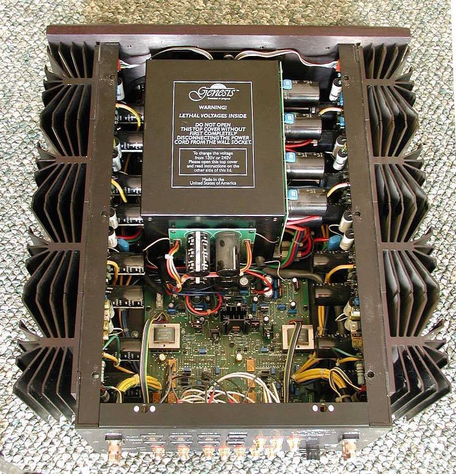
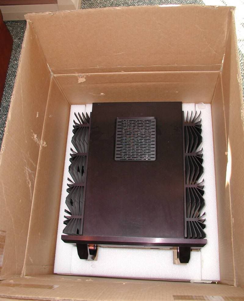
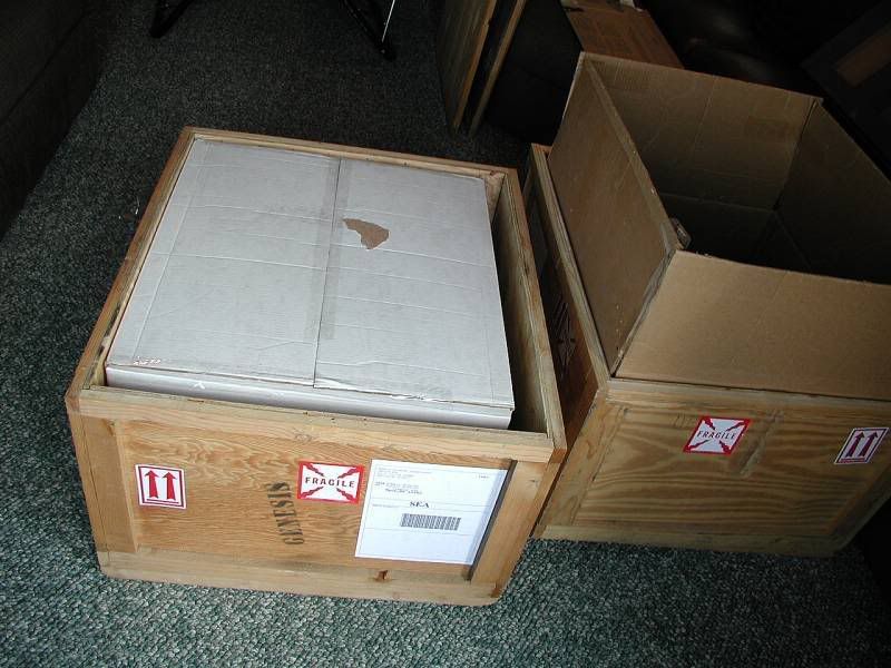
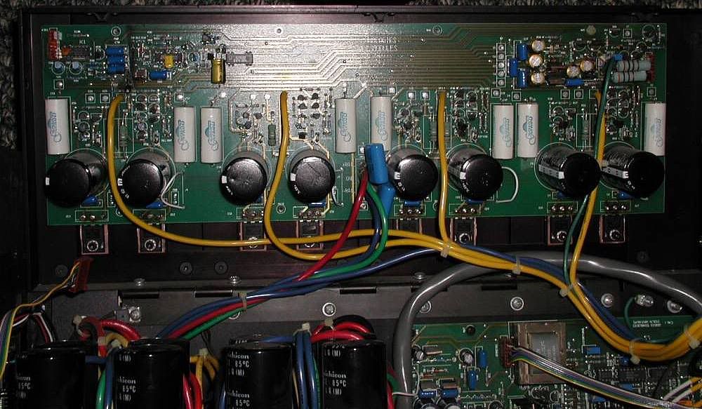
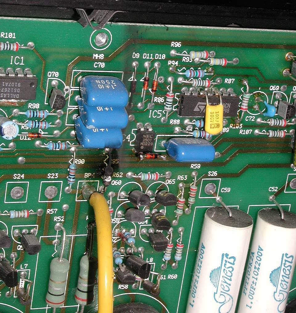
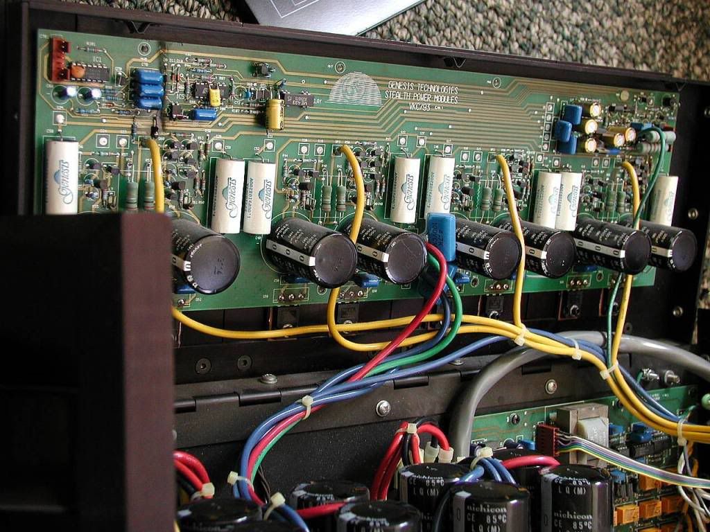
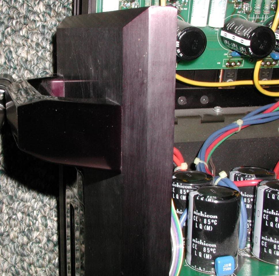
OS here's those pics we talked about. You should be able to see the burnt resistor and also the numbers on the transistors. You'll also notice that one box that holds the transformers is filled with epoxy or something and the other only has silicone around the outer edges of the transformoers. The silicone would be much easier to remove if you wanted to take the transformers out of the box.
If there's any other pics you'd like to see let me know.
The amp is physically designed to be very easy to work on. The sides are connected on the bottoms with a piano hinge so they flip open. It's pretty slick!
Pic 7 shows the 1 inch thick face plate we were talking about. 😱
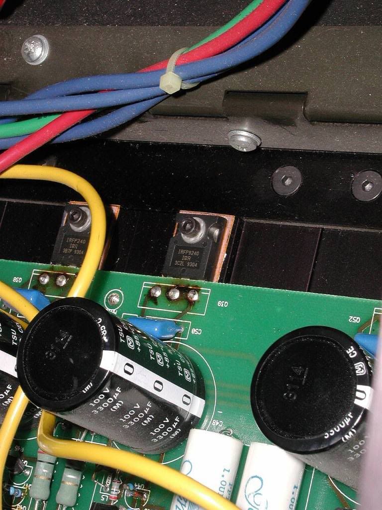
Pic 2 shows that the burnt resistor is located on the left side of the board. Pic 3 shows it up close.
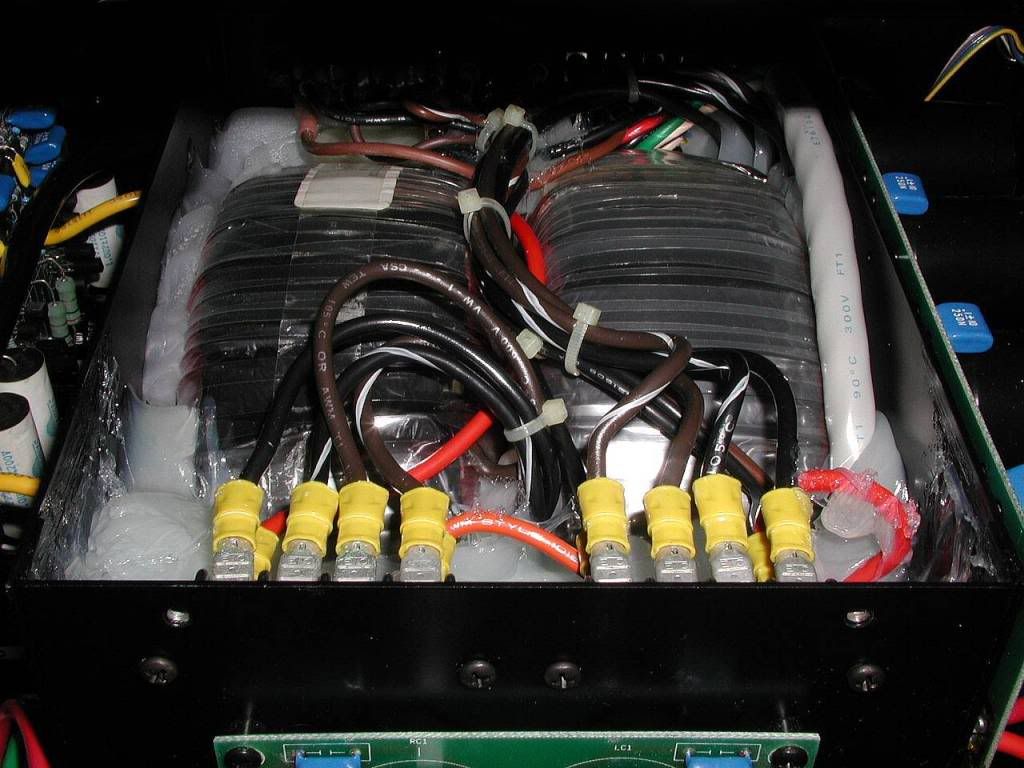
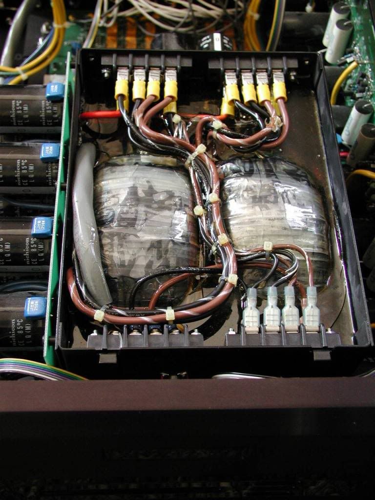
OS here's those pics we talked about. You should be able to see the burnt resistor and also the numbers on the transistors. You'll also notice that one box that holds the transformers is filled with epoxy or something and the other only has silicone around the outer edges of the transformoers. The silicone would be much easier to remove if you wanted to take the transformers out of the box.
If there's any other pics you'd like to see let me know.
The amp is physically designed to be very easy to work on. The sides are connected on the bottoms with a piano hinge so they flip open. It's pretty slick!
Pic 7 shows the 1 inch thick face plate we were talking about. 😱
Pic 2 shows that the burnt resistor is located on the left side of the board. Pic 3 shows it up close.
Good shots , don.
First the good... the OPS trannies are VERY common IRF vertical
mosfets, irfp9240/240. ( $3.15 apiece..) The little trannies (diff.
drivers) are mpsa 92/42 , all VERY common (I have 50ea. of those).
The board seems to be very clearly marked , so the ???'s in
the schema should be easy to "fill in"
The bad (not really so bad). It DOES look as through that
channel (all 4 amps) have failed (high current to all devices)
, so off to mouser we must go (8 new devices recommended).
Even as the board is clearly marked , the device numbers don't match , BUT , the topology is the same (can see the 68R
resistors , same drivers , output config.) So it is doable,
but difficult. (not a 1 hour repair)
All parts are widely available , easily to work on ... just
poor documentation.
OS
Pete, nice talking to you today. I will get these boxed & crated up and ship them out to you by the end of the month.
I really appreciate the help!
I really appreciate the help!
All figured out ..
I actually have this class A OPS working in LT.
The jerk@ss schematic was wrong (Q22 reverse biased) ,
but with the good photo's... all simulates well..
.ASC is in..
http://71.203.210.93/pdf1/Electronics/Projects/Audio_amp/Frugalamp/LT_simulations/
"genesis.asc" is the file.
For any interested in "scarfing" the topology.
One note.. circuit is very picky about operating currents in the
differentials , oscillated at first.. (R ??? in schema),
then .0001% bliss. 🙂
OS
Attachments
that's the stealth in simulation? THD seems nice and low!

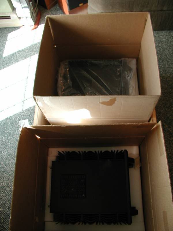
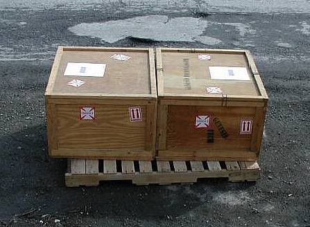
They're all boxed and crated up... sitting in the livingroom. I can send them anytime. You're gonna need a handtruck and/or 2 strong people to move these 200 lb. crates!
They're all boxed and crated up... sitting in the livingroom. I can send them anytime. You're gonna need a handtruck and/or 2 strong people to move these 200 lb. crates!
yes ,that is (simulation)
at 20k , at 1k it was .00001% !

I can see why these heat up the room.
@3 amps per OPS at the max bias that the CPU can set,
(1.5) at midpoint. So ....10 to 24 amps , a lot of heat.
According to the circuit schema , the bias is cpu controlled , can
you see a graphical representation (readout) of this on the (semi)working model??
OS
at 20k , at 1k it was .00001% !
I can see why these heat up the room.
@3 amps per OPS at the max bias that the CPU can set,
(1.5) at midpoint. So ....10 to 24 amps , a lot of heat.
According to the circuit schema , the bias is cpu controlled , can
you see a graphical representation (readout) of this on the (semi)working model??
OS
Yes. There is an LED section on the faceplate that shows the bias setting. It starts at 20 and goes up to 100 with the remote control or by pushing one of the "stealthy" buttons on the face.
Here's a video of the semi working amp. The bias is the larger number on the lower right. It's set at 20 in this video. The 2 smaller numbers above it are the R & L volume. Starting at 0 and you see them both go up to 2 when I hit the volume button on the remote.
http://smg.photobucket.com/albums/v517/esop/?action=view¤t=P3010001.flv
Here's the other amp trying to start up. It does this and then shuts itself off. This is the amp in the photos I posted above.
http://smg.photobucket.com/albums/v517/esop/?action=view¤t=P3010002.flv
- Home
- Amplifiers
- Solid State
- Genesis Stealth Amp