At the end of the day, may you post some figures as PN & AN (An = Amplitude Noise) of your system(s).
Picture Note:
PN figures given from the oscillator is one part, but how it performance at the final implementation is IMHO the beef question 😀
Hp
Picture Note:
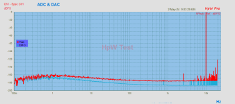
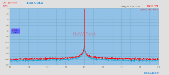
- SR about 40kHz, Signal as Fs/4 using ADC & DAC (all AKM chips) as with coherent master clock.
- ENF = Enhanced Noise Floor detector
- Both pictures use the equal sampled data but only using different scales.
- Any better to come 😀
- Work over years as a hug work in progress on HW & SW.
PN figures given from the oscillator is one part, but how it performance at the final implementation is IMHO the beef question 😀
Hp
Attachments

HpW, Impressive looking work. Not sure how much it has to do with music reproduction though. Doing something like scrambling of distortion in modulators so that it looks like noise to an FFT, then averaging most of it out before phase information is removed in order to better separate out PSS content for spectral display doesn't necessarily mean the system sounds good for music reproduction. It might sound pretty good or it might not.
Reclocker board is up and running since overnight. Sounds better than the old one:

NOTE:
One thing is starting to become apparent when using the boards of this thread to their utmost with a very high performance dac such as, for example, MarcelvdG's RTZ DSD dac. It is that under some conditions some audible crosstalk effects can occur when two clocks are installed and if all the clock signals running around the clock board are active. In the case when 22/24MHz clocks are used then its possible to disable (or never populate) most of the circuitry on the clock board, and thus keep active circuitry to a minimum. In that case most of the solder jumpers on the board can be left open, except for JP8 which should jumpered pin 2 to pin3, and except for JP9 which can be jumpered pin 1 to pin2.
The switched clock signals will then be available on J12, J13. One of those two connectors should have a u.fl cable running to the input of the PLL (J24). The other u.fl connector of J12, J13 should go to the Reclocker Board MCLK input.
This seems to work pretty well with Iancanada clocks or lessor. For sine wave clocks with squaring circuits, perhaps better to PM me for more detailed discussion.
Also, if some of the solder jumpers are left open then depending on how the clock board is populated, some CMOS inputs may be left floating. In that case a 10k resistor can be soldered to one of the open solder jumper pads and the other end of the resistor connected to ground to anchor the CMOS inputs safely.
Last edited:
What is this clock HpW?
//
Well well, the clock as OXCO as purchased and requires any modifications. In the clock is a key-point but requires additional tasks.
My ADC & DAC are purchased parts and required many modifications and to validate with new PCB's and even more to come.
BTW: All was batteries powered.
HpW, Impressive looking work. Not sure how much it has to do with music reproduction though. Doing something like scrambling of distortion in modulators so that it looks like noise to an FFT, then averaging most of it out before phase information is removed in order to better separate out PSS content for spectral display doesn't necessarily mean the system sounds good for music reproduction. It might sound pretty good or it might not.
It is more or less a trial as the state of 3 month ago. I did some NONE coherent too as expected some lower performance as using coherent. This
is as expected as 2 individual PN & AN clocks counts.
There is really an interested questions or beef question, how low the PN & AN figures have/should to be, so not detectable by Golden Ears.
But there is still ongoing research as on SW & HW 😀
Hp
On the "golden ear" question, as you put it, you might try playing back a well-recorded CD rip or hi-res recording through your dac and record it back into a wav file with your ADC. Then run DeltaWave to audibly compare the original and copy version files. After the Matching process there is a playback option where the differences between original and copy can be heard. Might have to turn up the volume control in DeltaWave a bit though. I would suggest to use a piece of music with vocals and with a good amount of percussion instruments (including cymbals). Piano is good too. Maybe like this one: https://www.dropbox.com/scl/fi/y761...lues.wav?rlkey=mwtkmno58e10lbbuv0frerhq7&dl=0
Listening to the waveform difference in Deltawave is not very meaningful as even the tiniest amount of misalignment or clock drift will result in large difference at e.g. transients.
Others have noted this too:
https://www.audiosciencereview.com/...ween-audio-cables-abx-test.53012/post-1916243
Others have noted this too:
https://www.audiosciencereview.com/...ween-audio-cables-abx-test.53012/post-1916243
They may think that's all it is, but they are not thinking of other things like time-smearing of transients or phase shifts caused by the output stage and or other stuff that doesn't show up well with fixed sine waves. However those sorts waveform changes may very well sound different. Those guys over there use oversimplified models, which is unfortunate.
The other thing about DeltaWave is all the FFTs tend to integrate out the significance of possibly audible short-time events. Also, spectral analysis based on FFTs often ignores phase information. Its well known that in some cases humans can hear phase differences. That's what the threshold of audibility for group delay is all about.
Besides, doesn't DeltaWave now have an option to correct for clock drift?
Last edited:
Deltawave can correct for clock drift. However DAC-to-ADC is an analog loop so there is always a waveform misalignment. Waveform difference depends on how well the waveforms can be re-aligned. Quite likely the re-alignment cannot be perfect.
OTOH spectra is calculated from the whole dataset (recording). So waveform misalignment does not play a role.
OTOH spectra is calculated from the whole dataset (recording). So waveform misalignment does not play a role.
Maybe you should also describe how you manage to use 10MHz MCK with USB-I2S 😉Well well, the clock as OXCO as purchased and requires any modifications. In the clock is a key-point but requires additional tasks.
My ADC & DAC are purchased parts and required many modifications and to validate with new PCB's and even more to come.
BTW: All was batteries powered.
The spectra being for the whole dataset (recording) seems to me a way to miss a lot of short time differences, which is because phase information and or signal correlated noise is ignored. For example, a dataset can be reconstructed from and FFT by performing an inverse FFT. However it doesn't work if the phase information has been discarded. Its no longer a unique fingerprint.
Okay, that's good.
However I'm still not buying the explanations by other guys over there. I could hear a difference between files on electrostatic speakers at moderately high volume. The difference playback feature in DeltWave sounds like a reasonably credible, pretty close rendition of the file differences to me. Thus, I am persuaded by the physical evidence rather than what looks to me like oversimplified theory by the guys over there.
Other people are of course free to believe whatever they want.
Some member at ASR has uploaded recordings made with Mola Mola Tambaqui and DCS Scarlatti using RME ADI-2 FS as ADC:
https://www.audiosciencereview.com/...ve-null-comparison-software.6633/post-1651658
The waveform difference is much more pronounced compared to the recordings of PCM2DSD at RTZ thread. Also the null is much worse.
https://www.audiosciencereview.com/...ve-null-comparison-software.6633/post-1651658
The waveform difference is much more pronounced compared to the recordings of PCM2DSD at RTZ thread. Also the null is much worse.
Interesting. I hear jitter in the copies, but they aren't both equally bad. The bright cutting edge effect on female vocals on the full OXCO version really sounds like a type of jitter. I believe its jitter because its not on the original recording, and IME the particular effect goes away when ferrites and nonlinear caps are removed. Sure would like to inspect that system close up.
RME ADI-2 FS uses a PLL clock which may be the reason. Anyhow as I said in Deltawave those files result in much louder waveform difference which sounds very boomy. So using Deltawave waveform difference as an indicator of sound quality is questionable.
Hi Mark,
Just wanting to tell that you did a great job in this open source project.
This is really diyaudio at its highest level.
Hans
Just wanting to tell that you did a great job in this open source project.
This is really diyaudio at its highest level.
Hans
Hi Hans,
Thank you so much. It means a lot to hear that coming from you.
Mark
Thank you so much. It means a lot to hear that coming from you.
Mark
Hmmm... About twice as many Reclocker Board schematic downloads as gerber and KiCad file downloads. Hopefully everyone understands that in some cases layout can be just as important as the schematic. IOW, layout can be critical to good results. That's all.Attached are the open source project files for the Reclocker Board v1.2
- Home
- Source & Line
- Digital Line Level
- General Purpose DAC Clock Board