I hear you Patrick! I'm still riding sewup tires so they handle higher pressure than a tire and tube.
Just keeping the conversation going Earl. Got anything new to add about horns. I see you do what I would say I pioneered with urethane years ago. Do you actually make your own horns, mold the urethane? I used and still use high density 65pcf rigid foam for all the things I have done. If you don't make your own tooling things can get rather expensive fast.
Just keeping the conversation going Earl. Got anything new to add about horns. I see you do what I would say I pioneered with urethane years ago. Do you actually make your own horns, mold the urethane? I used and still use high density 65pcf rigid foam for all the things I have done. If you don't make your own tooling things can get rather expensive fast.
Yes, I mold my own horns but the polyurethane is not foam. I make some of my own tools and buy some parts from a tool and die house.
One good method:Is there a golden rule for XO slopes for OSWG / Conical horns?
You can cross higher, electrically first order, and if you tune it right, it can allow you to use the same cap for protection with about a 3rd order final slope, as well as to provide the constant directivity EQ- but you may still need some impedance compensation etc, and it does demand a robust driver.
Is this assuming the waveguide creates a 2pole roll-off?with about a 3rd order final slope
Is there a golden rule for XO slopes for OSWG / Conical horns?
The short answer is no, there is no golden rule - whatever works. Since the passband of a waveguide is not flat (it falls with frequency) the compensation is really part of the crossover.
Is this assuming the waveguide creates a 2pole roll-off?
It's not really that simple- you've got the highpass power characteristic of the compression driver, which ends at about 2nd order, but then the cutoff of the waveguide on top of that. It winds up being a multi-stage cutoff characteristic unless you really hammer it with the crossover, 3rd is just a rule of thumb for the slope immediately below where you'd typically want to have equal amplitude response (the crossover point but not the electrical crossover point as far as the C.D. is concerned).
I hope that helps, it's just my experience and others may feel otherwise. The behavior of the CD/Waveguide/Horn combo will really define what you have to do, if you had to reduce the low end cutoff of the compensation cap by bypassing it with a resistor, for example, you'd need to tack on another high-pass stage to protect the driver.
The behavior of the CD/Waveguide/Horn combo will really define what you have to do ...
That's really the point, there is no hard and fast rules - too many variables.
Member
Joined 2003
Hi Earl,
I believe you've stated that the wavefront produced by most compression drivers is not flat.
What are the typical wavefront shapes produced by good quality CDs with circumferential phase plugs?
Thanks,
I believe you've stated that the wavefront produced by most compression drivers is not flat.
What are the typical wavefront shapes produced by good quality CDs with circumferential phase plugs?
Thanks,
I don't have much data on this, but the few measurements that have been made show that the wavefront is not flat. Flat, of course, is a relative thing - relative to the wavelengths. So this is really only an issue at the higher frequencies where the HOMs start to appear. And even then we are talking about relatively small variance from flat, maybe 10-20% at most. Flat is the intent and it is mostly achieved, but there are errors in typical devices.
Is there a relation between the exit angle and the wavefront shape?
One would think that the wavefront would be perpendicular to the throat wall at exit.
I think the OS formula assumes this.
One would think that the wavefront would be perpendicular to the throat wall at exit.
I think the OS formula assumes this.
The lowest mode has to be perpendicular to the walls, but not the higher ones (the HOMs). They reflect off the walls. The OS/waveguide formulation does not actually assume this, which is why it predicts HOMs. No other theory does this, i.e. all other theories assume the wavefront is perpendicular. But we know for a fact that is not always the case. This assumption is the root cause of the errors in Webster's work.
No other theory does this, i.e. all other theories assume the wavefront is perpendicular.
This is a bit confusing, Earl. From what I have learned, the wavefront has to be perpendicular to the wall if the boundary condition is zero admittance (hard wall, which I would say applies pretty well to the metal internal flare of a compression driver). The normal derivative of the pressure at the wall should be zero. If the wavefront is not normal to the wall at the wall, the wall must have a non-zero admittance (if you disregard the viscous boundary layer). Waveguide theory should be able handle this by changing the boundary conditions, but this must be the first time I have seen you mention it as a unique feature of waveguide theory.
One could say that horn theory assumes that the wavefront can be described by an arc between the two wall normals, but as we both know, this is not true due to the presence of higher order modes.
Still the hard wall boundary condition dictates a zero normal derivative at the wall for each mode.
You say that only the waveguide formulation does not assume that the wavefront is perpendicular to the walls. What theories, apart from horn theory, do? Leaving aside horn theory, I thought this was only a matter of setting the correct boundary conditions?
Regards,
Bjørn
Dr. Geddes,The lowest mode has to be perpendicular to the walls, but not the higher ones (the HOMs). They reflect off the walls. The OS/waveguide formulation does not actually assume this, which is why it predicts HOMs. No other theory does this, i.e. all other theories assume the wavefront is perpendicular. But we know for a fact that is not always the case. This assumption is the root cause of the errors in Webster's work.
Do the planar sources (ribbons, AMT, etc) produce flat wavefronts?
Bjorn
I am not sure that you are making things any clearer. Does not a wave that impinges on a hard surface at an angle meet the boundary condition of zero normal velocity? It is the sum of the incident and reflected waves that meets this condition. The same is true of higher order modes in a straight duct. Why would it be different for a flared duct?
I think the confusion here is that we usually thinks of a wavefront as just the incident wave not the incident wave plus its reflected wave. The incident wave is not perpendicular to the wall but the sum of the incident and the reflected wave is, but only right at the wall. So it depends on what you are talking about. There is no reflected wave for the first mode so we don't tend to think in these terms.
Because the HOMs which reflect off the walls, must do so at both sides of the device, only a very unique and precise wave will meet both of the conditions. So all of the theories have a normal boundary condition, but only if the surface is a separable coordinate system can you find those unique solutions to the HOMs. Webster's theory cannot do that and hence their existence was unknown from that theory.
Last edited:
Dr. Geddes,
Do the planar sources (ribbons, AMT, etc) produce flat wavefronts?
For the most part. Its too bad that they are not round. There are no square waveguides that accept a flat source - well elliptic cylinder, but that does not flare in the vertical axis.
To fully understand, FEM computation is more appropriate to calculate static pressure and dynamic pressure variation as the wave propagates. Then adjust the shape so that the propagation is the best that can be achieved.
My wave guide studies are currently sort of a background task now, until I can get some other work finished. Sometimes looking back through old tests and analyses might help generate some more ideas, which is all I can do at the moment. But I do hope to get a new design into testing.
My wave guide studies are currently sort of a background task now, until I can get some other work finished. Sometimes looking back through old tests and analyses might help generate some more ideas, which is all I can do at the moment. But I do hope to get a new design into testing.
Last edited:
I have been working on this issue recently. Using oil based clay to modify the exit grill on an Airborne RT 4001 amt with the front bezel removed. Other than pattern flip which will be resolved in the next waveguide mod changing the exit made very little difference in responce/distortion so the requirement for a custom phase plug was a non issue. BTW the exit height was reduced from the 5 slots to 3, changing it from ~1.5" to 3/4". Width was left unchanged at 1".Dr. Geddes,
Do the planar sources (ribbons, AMT, etc) produce flat wavefronts?
Picky (not so) little problem when squeezing an amt between two 6.5" midbasses. Gap between the two is 1.5" and physically time aligned z axis. The resulting eliptical waveguide will be similar to an eJMLC 1000. MiniDSP controls things.
Just to clarify: when you say that waveguide theory doesn't assume that the wavefront is perpendicular to the wall, you mean the incident wavefront, and not the total field?
so maybe we can get a actual thoughtful comment on this now?
sorry Earl but its getting difficult to sort out what you're objecting too and the reasons
I thought you did think wavefront pressure, velocity shape was important in the throat
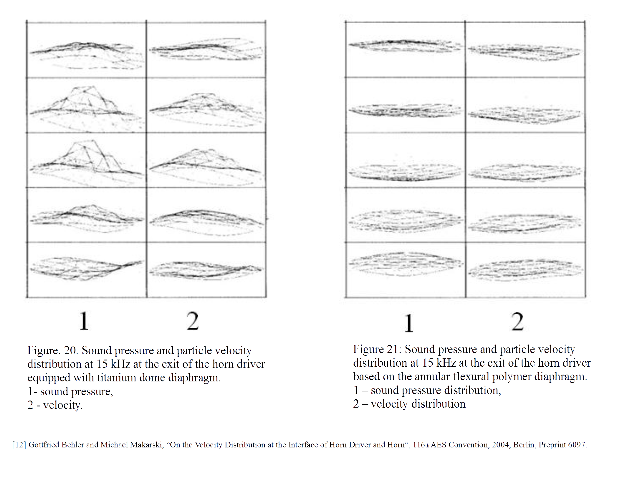
did you comment on the paper/image from http://www.diyaudio.com/forums/multi-way/103872-geddes-waveguides-686.html#post3945668
isn't the right side better in your own terms?
why or why not?
- Home
- Loudspeakers
- Multi-Way
- Geddes on Waveguides