I would think that pricing is not really taking into account the mold costs and setup chargers you would incur. I would suspect you would need to make many 100's if not 1000's to get the cost per unit that low.
For example, i contacted a company capable of thermoforming uploaded designs at what they said was the best pricing around. For less than 50 I had an initial 200 dollar setup fee for items in the size I wanted. What I had designed was a record mat made of a plastic material with a dish toward the center, I figured if I could get them cheap enough, it might be something to sell on ebay, and get me a nice record mat that did what I wanted. Cost per unit, on top of that 200 dollars, was 25 dollars per unit. My total cost, after shipping, was around 35 dollars per item. This was for basically a 4mm disc, and the price was still only so low because the form was so simple for them to make.
Yes the form, labor, and equipment are additional costs (and there will be quite a few more costs as well).
Per unit retail (..depending on size), would be multiples of the material cost.. so that less than 10 US I mentioned before would likely factor into 40-50 US retail (..and again, that's for a waveguide that is modest in size). On the other hand as you go to large dimensions you become more competitive (when compared to the market). Many of the larger format horns/waveguides retail for more than 200 US per unit.
If the waveguide is small enough and conical in shape you'd probably be better-off having plastic milled/turned. (..similar to what Troels had fabricated for the Audax TW034.. which I believe is priced around 40 US per unit, but doesn't need back-filling.)
The thing I'm worried about the cutomer backfilling is how much it will deform the shape of the wave guide. Some backfill material expands in the hardening process. Then, there is also the look quality and the scratch resistance of the final thing.
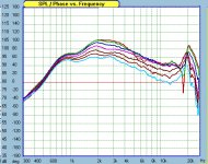
Finally got time for a little rough measurements.Update. From a whole bunch of data from sims, I decided that the configuration for this data (23cm diameter at baffle blending edge) is interesting enough to test. Pretty close to an OS. What really worries me is that manufacturing tolerances seem pretty critical.
0~45 deg in 7.5deg increments. As we can see, not quite the same as the sim. So we can explore a bit deeper to see whether differences between model and physical configuration plays any important effect.
Attachments
Last edited:
Interesting that the hole on-axis is not at all represented by the simulation. I would look at the mouth termination differences for this.

Interesting that the hole on-axis is not at all represented by the simulation.
Where is the hole? I don't see it. Do you mean the sharp dip near the top?
I'm sure he means the dip between 5K~7KHz. I'm thinking it's due to the abrupt cut after lip reaches 180 deg.
The sim is plended into an infinite baffle.
Thats why the sim is not acurate.
Where is the hole? I don't see it. Do you mean the sharp dip near the top?
If you flatten the response, and plot on a normal scale (50 dB instead of 90), you will see a dip right on axis, 4-7 Khz as Gearge said.
Modifying the lip of the sim to cut back 2cm abruptly, not only a hole is created, but also the deep notch location is closer to the actually measured location. This is quite an interesting find.
Since the model has to be axisymmetric, totally accurate sim is not possible for comparison. But, it seems termination of lip after 180 deg is also critical for a good response. So the narrowest baffle might not be the best kind of termination.
Since the model has to be axisymmetric, totally accurate sim is not possible for comparison. But, it seems termination of lip after 180 deg is also critical for a good response. So the narrowest baffle might not be the best kind of termination.
Attachments
Last edited:
Can you sim a spherical curve transition from tangent and continue through 270 degree rotation? (ie., 225 degrees from axis) 
I'm sure he means the dip between 5K~7KHz.
Ah, thanks! I did not see that was the 0 degree line dipping there. Got it now.
(sometimes red lines don't show well on LCD monitors).
So the narrowest baffle might not be the best kind of termination.
Precisely - I have been say that for a long time.
In the past, I have simmed not only that, but actually free standing 1M in front of baffle. The results were not that accurate. But What would be interesting is to do a little bit of lip and determine how lip curvature might effect response. This is what I plan to do in the next step. At least, up to now, the WG and throat section seem to be adequate enough.Can you sim a spherical curve transition from tangent and continue through 270 degree rotation? (ie., 225 degrees from axis)
Sure, but now I am interested in figuring out how to determine the smallest adequate shape and width. Some parts of the data look suspicious.Precisely - I have been say that for a long time.
Now, if the lip further protrudes 8cm from the baffle instead of 2cm...Modifying the lip of the sim to cut back 2cm abruptly, ...
Attachments
I don't think its a "dip" at all.
Rather I think it's a matter of gain below the area you would consider a "dip".
Rather I think it's a matter of gain below the area you would consider a "dip".
A dip or a gain to all the other curves? Let me see - sounds kind of irrelavent to me. Is a mountain high or is it just that all the other ground is low? Or, that's not really a valley, it's just that the ground rises up on either side.
A dip or a gain to all the other curves? Let me see - sounds kind of irrelavent to me.
I didn't make the statement for semantics.. One perspective describes only a problem - without an explanation. My perspective *perhaps* suggests the reason for that problem.
- Home
- Loudspeakers
- Multi-Way
- Geddes on Waveguides