I'd still expect that quite a lot could be done with edge treatments.
I'll be doing some with/without measures soonish. Like the miniature foam plug?
Seems to me that large-scale formed lossy foam could provide quite a lot of changes to the mouth, likely sufficient to offset the dip, at least somewhat.
I'll be doing some with/without measures soonish. Like the miniature foam plug?
Seems to me that large-scale formed lossy foam could provide quite a lot of changes to the mouth, likely sufficient to offset the dip, at least somewhat.
As far as I can see, the curves are are overlaping.I was talking about 4 kHz where a clear hole is evident in the measurements. Looks like several dB, at least as bad as any one my waveguides. The scale is a real problem, makes accurate comparisons impossible.
Attached is the Summa on the same scale.
You made claim to such success earlier and now, when pressed, the story seems to have changed.
Your picture only shows up 2 inches wide on my screen. Mine is a real lot larger. 😀
That device won't exhibit a dip.
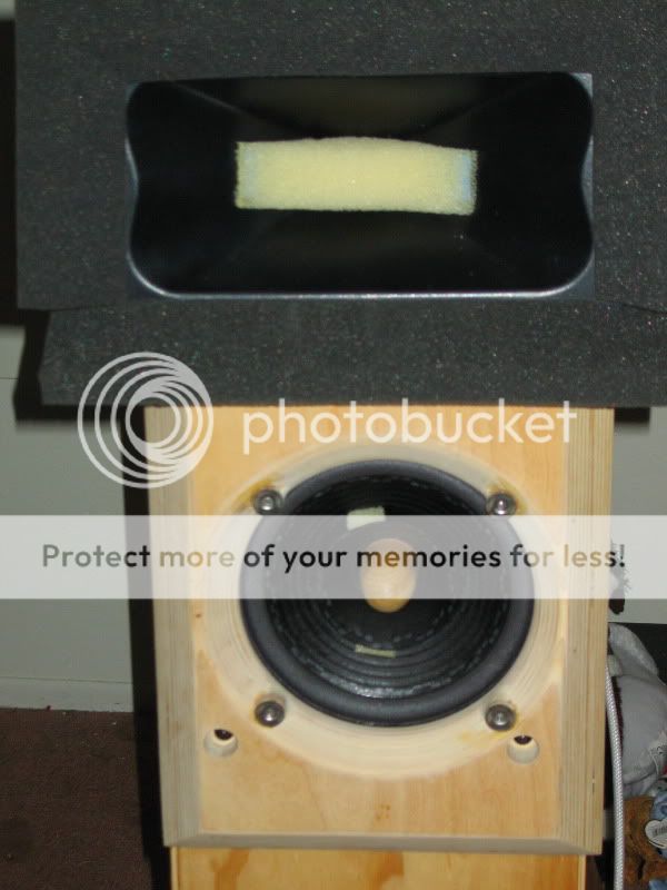
Oh, naturally. The idea with THIS device is to soften the mouth diffraction. The foam is a heavy but open-celled type, so it should be a nice mix to act as a "softened" edge termination.
My point, though, is that one could use some larger foam pieces to create some significant acoustical asymmetry at the mouth. Perhaps one top and one bottom to lend a little loss in the vertical plane as well?
Perhaps one top and one bottom to lend a little loss in the vertical plane as well?
I like that idea.
As far as I can see, the curves are are overlaping.
Your picture only shows up 2 inches wide on my screen. Mine is a real lot larger. 😀
I guess you see what you want to see. The dip is obvious to me.
For some reason I could not seem to upload a bigger image. Don't know why that is.
This one is better.
Attachments
I like that idea.
Well, once I get my attempt at OS guides done (these things have a heck of a lot of resin equity in them!) I can test it. My coworker has to ship laptops quite often, and the foam that's used is a relatively dense open-cell variant- perfect for this app, where a little reflection isn't such a bad thing. Naturally one would want to be more careful with the edges. In the pic shown the foam is all beveled so the angles are 45 rather than 90 deg, and due to the sloppy cutting method (my hot wire cutter leaves something to be desired!) there's some variance there too. It's hard to tell from the pic, but the foam is proud about 1.25" from the surface of the horn flange.
For easier comparison, here is slightly equalized graph of one waveguide
http://www.diyaudio.com/forums/multi-way/103872-geddes-waveguides-320.html#post1887746
and a comparison brought into the same scale.
I removed some curves so that both show 60deg range.
BTW, the curve on the top has a mouth of about 18cm diameter measured at point tangent to baffle.
http://www.diyaudio.com/forums/multi-way/103872-geddes-waveguides-320.html#post1887746
and a comparison brought into the same scale.
I removed some curves so that both show 60deg range.
BTW, the curve on the top has a mouth of about 18cm diameter measured at point tangent to baffle.
Attachments
Last edited:
For easier comparison, here is slightly equalized graph of one waveguide
and a comparison brought into the same scale.
I removed some curves so that both show 60deg range.
BTW, the curve on the top has a mouth of about 18cm diameter measured at point tangent to baffle.
You keep choosing different data, but yes, that is a comparable device to my smallest waveguide. Its actualy quite good, maybe too good. I don't see the kinds of problems that I expect to see in all measurements, and mounting situations. I can never get data as clean as what you show.
How is your waveguide mounted? IB? What distance? I hope your not in closer than 1 meter and hopefully its more like 2-3 meters. These things make a huge difference. Nearfield of a horn is totally misleading.
I'd still like to see data out to 90 degrees and a hi-res polar map. You never answered my question - do you have this data?
Last edited:
Reading this thread, seems a lot of people take a large issue with a very narrow hole in the response. I'd like to ask what is the big issue? Why is this so important? I can't figure it out. Seems it's so narrow it wouldn't be audible. Am I wrong?
Sonngsc, that graph looks incredible! Care to share the contour?
Dan
Sonngsc, that graph looks incredible! Care to share the contour?
Dan
It's 2am, and I'm getting ready to sleep.You keep choosing different data, but yes, that is a comparable device to my smallest waveguide. Its actualy quite good, maybe too good. I don't see the kinds of problems that I expect to see in all measurements, and mounting situations. I can never get data as clean as what you show.
How is your waveguide mounted? IB? What distance? I hope your not in closer than 1 meter and hopefully its more like 2-3 meters. These things make a huge difference. Nearfield of a horn is totally misleading.
I'd still like to see data out to 90 degrees and a hi-res polar map. You never answered my question - do you have this data?
http://www.diyaudio.com/forums/multi-way/103872-geddes-waveguides-320.html#post1887746
The waveguide was mounted stand alone on a single pole speaker stand.
This one paricular waveguide has a rolled back lip 180deg.
Measuring distance is 1meter measured from the diaphragm. Measurements are rotated about the AC as close as possible so that the AC distance remains contant. If the rotation is about the center of the mouth, then as the wave guide is rotated, the AC distance is reduced, thus plots will seemm to have better directivity.
I have to check the measurement computer to find out. A task for tomorrow. Most probably 60deg is the most I have. May I ask what is the significance of looking at 90deg? I did 75deg on a different one, and really saw no point going further.
I don't think the hole is important.Reading this thread, seems a lot of people take a large issue with a very narrow hole in the response. I'd like to ask what is the big issue? Why is this so important? I can't figure it out. Seems it's so narrow it wouldn't be audible. Am I wrong?
Sonngsc, that graph looks incredible! Care to share the contour?
Dan
I have posted a contour way back when doing the BEM simulations. Basically it was an OS throat with a LeCleach expansion. the OS throat was probably based on a 65deg calculation, but I won't swear by it. It does not sound good enough because the acoustic loading was not correct for that driver. But it seems foam might change that a bit. It's just that I have this fit about puting something in front of the diaphragm.
I don't think the hole is important.
I have posted a contour way back when doing the BEM simulations. Basically it was an OS throat with a LeCleach expansion. the OS throat was probably based on a 65deg calculation, but I won't swear by it. It does not sound good enough because the acoustic loading was not correct for that driver. But it seems foam might change that a bit. It's just that I have this fit about puting something in front of the diaphragm.
Interesting! I'd love to know how you guys build these things. I have ideas, but they all seem complicated and difficult to make a good looking one.
Dan
Reading this thread, seems a lot of people take a large issue with a very narrow hole in the response. I'd like to ask what is the big issue? Why is this so important? I can't figure it out. Seems it's so narrow it wouldn't be audible. Am I wrong?
Dan
People always need something to complain about. The hole is even less important when you consider that I don't even try for a flat response on-axis because the listener should never be on axis if the speakers are toed properly. So they will never be in this hole. Of course its not audible unless your ear is exactly on-axis.
It's 2am, and I'm getting ready to sleep.
http://www.diyaudio.com/forums/multi-way/103872-geddes-waveguides-320.html#post1887746
The waveguide was mounted stand alone on a single pole speaker stand.
This one paricular waveguide has a rolled back lip 180deg.
Measuring distance is 1meter measured from the diaphragm. Measurements are rotated about the AC as close as possible so that the AC distance remains contant. If the rotation is about the center of the mouth, then as the wave guide is rotated, the AC distance is reduced, thus plots will seemm to have better directivity.
I have to check the measurement computer to find out. A task for tomorrow. Most probably 60deg is the most I have. May I ask what is the significance of looking at 90deg? I did 75deg on a different one, and really saw no point going further.
One meter from the diaphragm is very close. This is going to smooth things considerably and this distance cannot be done with a crossover in place without serious problems.
I rotate about the AC as well, but I wouldn't jump at the conclusion about the "better directivity".
It's just that I have this fit about puting something in front of the diaphragm.
And this is because ...? You have some love affair with looking at a diaphragm? (I guess that it depends on where it is!
 ) I've heard this comment before and I don't get it.
I'd love to know how you guys build these things.
Dan
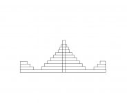
This could be the basis
Smooth it out by sanding, and plaster
Put fiberglass on it
Sand again
And so forth
Needs to be painted with mold paint
Wetsanded and and vaxed
Then you have a mold
If you want a pro mold I would do a 2-part mold
Its easy, but you need to know how
And you need a counterpart which should be smooth on the outside instead
The mold is made upon that
Size changes and needs to be calculated
Its just work
Attachments
Oh, naturally. The idea with THIS device is to soften the mouth diffraction. The foam is a heavy but open-celled type, so it should be a nice mix to act as a "softened" edge termination.
My point, though, is that one could use some larger foam pieces to create some significant acoustical asymmetry at the mouth. Perhaps one top and one bottom to lend a little loss in the vertical plane as well?
You possibly should start to look at horns to be "diffraction alignment" device as I several times pointed out elsewhere.
This way you are not in an endless battle *against* diffraction – that never can be won anyway.
Having a closer look at absorptive material at the mouth you might come to the surprising conclusion that it actually does the opposite of what you possibly want to achieve.
Simply imagine your foam treatment to be 100% acoustically absorbent – and immediately it becomes clear that you created kinda sharp 180 deg turnover.
Sure – the foam you use is hardy any 100% absorptive – but just keep the picture and its impacts in mind....
😉
Michael
It "impacts" in my mind that there is a 100% logical and descriptive disconnect here.
If the material is 100% absorptive, then what is going to 'turn around the turnover'?
If the material is 100% absorptive, then what is going to reflect or refract?
0 - 0 = 0 0 + 0 = 0
Simply imagine your foam treatment to be 100% acoustically absorbent – and immediately it becomes clear that you created kinda sharp 180 deg turnover.
If the material is 100% absorptive, then what is going to 'turn around the turnover'?
If the material is 100% absorptive, then what is going to reflect or refract?
0 - 0 = 0 0 + 0 = 0
It "impacts" in my mind that there is a 100% logical and descriptive disconnect here.
If the material is 100% absorptive, then what is going to 'turn around the turnover'?
If the material is 100% absorptive, then what is going to reflect or refract?
0 - 0 = 0 0 + 0 = 0
I think that he means that 100% absorptive is also a reflective boundary condition (called pressure release p = 0 as opposed to rigid velocity = 0). To not reflect at all it needs to be the same impedance as free space.
But then again, I gave up trying to understand Michael a long time ago.
Last edited:
You possibly should start to look at horns to be "diffraction alignment" device as I several times pointed out elsewhere.
This way you are not in an endless battle *against* diffraction – that never can be won anyway.
Having a closer look at absorptive material at the mouth you might come to the surprising conclusion that it actually does the opposite of what you possibly want to achieve.
Simply imagine your foam treatment to be 100% acoustically absorbent – and immediately it becomes clear that you created kinda sharp 180 deg turnover.
Sure – the foam you use is hardy any 100% absorptive – but just keep the picture and its impacts in mind....
😉
Michael
If it's 100% absorbtive..... it has the virtue of creating a very effective horn extension as far as directivity is concerned, just without the gain. I'm not sure what your concerns are. Naturally a boatload of foam is not a total panacea but used appropriately, as in my image, it's potentially a significant improvement over the sharp mouth transition, and should reduce ripple significantly.
- Home
- Loudspeakers
- Multi-Way
- Geddes on Waveguides