Now add a premium to that because of the elliptical tooling costs and you are looking at a pretty big number.
If I should do it, it would cost the same to me, round or elliptical 😀
Anyway, if you think in numbers, and you sell a lot more =
 XXXX, then you might reconsider
 And Im certain more people would order if having elliptical
Try announce both round and elliptical, at close to same price, and see which one is ordered 😉
If I should do it, it would cost the same to me, round or elliptical 😀
Anyway, if you think in numbers, and you sell a lot more =
And Im certain more people would order if having elliptical
Try announce both round and elliptical, at close to same price, and see which one is ordered 😉
Basically in the Hi-end speaker business ALL designs are such low volume that "economies of scale" don't apply. That makes your comments basically null and void. Make them completely mediocre, dirt cheap, and sold at Best Buy at 50% markup and you can use that kind of business model. But if sound quality is going to be a significant factor then you will have to give up on those kinds of concepts.
I agree if it means ordering everything from a third part, and pay fore it
But being "small" I suppose thats no option anyway
Making molds yourself, means you wont get payed fore that, on short terms
Lots of hours, and little pay
I know its not so, but it could make the difference whether you sell anything or not
I have a friend who started a company thinking he should get payed fore every minute
He lost most of his customers
Many people ask fore good looks, and elliptical waveguide might be one way to achieve it
Ofcourse thats subjective
700-800mm wide, I would sure like to own a pair
And how much of a premium would you pay for the elliptical - and put down the cash of course, not just say $XXXX
Keep in mind the current cost of a Summa and the cost differences due to size of the other models. Now add a premium to that because of the elliptical tooling costs and you are looking at a pretty big number. Make your proposal above big enough and you'll have your speakers by spring🙂
Shift perspective for a moment.
I'm not sure you can NOT do the elliptical version. Not because it will necessarily result in a markedly superior product, but rather to maintain a competitive advantage.
Copying any conical design is not that difficult, either from a DIY effort or a commercial one. Copying an eliptical however.. FAR less easy to do.
Then there is the fact that yes, it should offer some measurable benefits.
Then there is the fact that others *want* this. (..and if you can't supply what others want, your market will continue to decline over time.)
To do it competitively though you'll need to alter your manufacturing method (..at least based on what you have described).
For a relatively large object with such a complex shape AND considering small production runs requiring low cost/minimal labor there really is only one solution I can think of: Thermoforming. 🙂
I have published measured data on Rod Elliots site that demonstrates constant directivity behavoir of a dome driven device.
These devices display sub milli second time delay effects, unlike o.s. waveguides.
In my opinion going to the elaborate length of stuffing the gadget with foam to get a 6db. attenuation of these effect, when you can just use a dome in a shallow horn that does not have them and is easier cheaper to do and sounds just as good, is a waste of time.
rcw.
I gave up on using domes in waveguides a few years ago, but I think I'm ready to take another crack at it. I personally believe that a compression driver is a better solution, but I have a unique problem, and I can't find a way to solve it that doesn't involve a dome tweeter. Here's the situation:
I've built a ton of horns and waveguides, primarily for automotive use. When I first started, I built them full size. We're talking huuuge ol' horns that make the car basically undrivable. This is back in the 90s. As I began building waveguides, I found that you could use boundaries to extend the waveguide. And I don't mean an inch or two. I'm talking about removing over 75% of the waveguide.
Here's the problem I'm running in to: The size of the compression driver itself is really becoming an issue. I can't find compression drivers small enough to fit into corners. The best solution that I've found so far is to bend the throat of the waveguide, so that the compression driver enters at a 45 degree angle. But it's tricky, because the bend creates a dip in the frequency response, and the dip gets deeper as the bend gets bigger. (IE, if the compression driver enters the waveguide at a ninety degree angle you get a big fat dip due to a reflection off the wall of the waveguide.)
An externally hosted image should be here but it was not working when we last tested it.
Again, not saying that this is a good solution for the home, where depth isn't a problem. But my application is rather unique, and I simply can't think of another way to solve this.
By using a dome tweeter I will lose a great deal of efficiency, reduce power handling, and increase distortion. On the upside, it's smaller, looks better, and costs less. I have a hunch that a phase plug could be built to improve the high frequency polar response. Basically get the dome to behave more like a compression driver, and less like a dome.
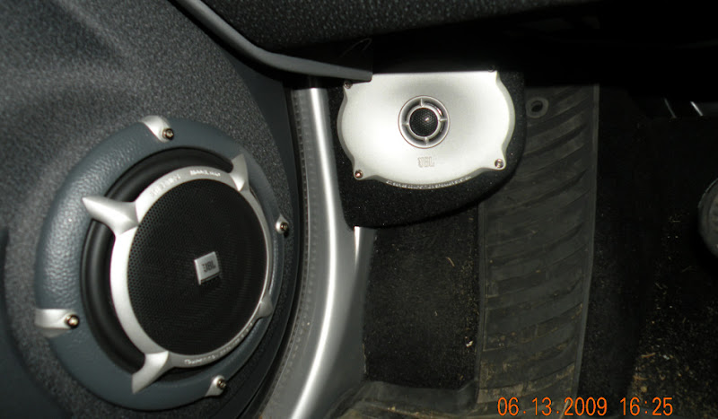
Here's a pic of JBL's top of the line components, which use a waveguide that looks suspiciously like an elliptical oblate spheroidal. My design would be similar to this, but using the windshield to bring the soundstage to eye level, and to extend the curve of the waveguide. (In other words, my waveguides will have a narrower coverage angle than JBL's.)
So I would end up with a waveguide that uses the oblate spheroidal curve, but with a footprint that's about 75% smaller than the waveguides I am already using. I haven't decided yet if it will be a Unity. There *is* enough room to mount a couple of midranges to extend the response. The primary goal will be to reduce the waveguides size to the smallest footprint possible, and use the existing boundaries to extend the curve.
Anyone care to comment on these plans?
To do it competitively though you'll need to alter your manufacturing method (..at least based on what you have described).
For a relatively large object with such a complex shape AND considering small production runs requiring low cost/minimal labor there really is only one solution I can think of: Thermoforming. 🙂
I have to agree. I have always thought that changing manufacturing methods, to thermoform or similar, as you say would be the way for more people to experience a Gedlee speaker. These cabinets are what I envisaged, allowing for appropriate changes to thickness and structural rigidity.
...
If it has an elliptical waveguide I'd like to subscribe to the preorder list now 😉
Best, Markus
Now how impractical this is. Certainly hope more seriously proffesion discussion continues.And how much of a premium would you pay for the elliptical - and put down the cash of course, not just say $XXXX
Keep in mind the current cost of a Summa and the cost differences due to size of the other models. Now add a premium to that because of the elliptical tooling costs and you are looking at a pretty big number. Make your proposal above big enough and you'll have your speakers by spring🙂
 😀
😀Member
Joined 2003
The only WG simulation tools I have available are Axi-Driver and Hornresp. In other words, I can sim only round WGs.
Any opinions on whether a 6:5 H:V aspect elliptical mouth would be enough to break up the on-axis dip apparently inherent in axi-symmetric waveguides? If not, what ratio would do the job? I would like to make the aspect ratio as tight as possible, but eliminating the dip has priority over aspect ratio.
Any opinions on whether a 6:5 H:V aspect elliptical mouth would be enough to break up the on-axis dip apparently inherent in axi-symmetric waveguides? If not, what ratio would do the job? I would like to make the aspect ratio as tight as possible, but eliminating the dip has priority over aspect ratio.
The only WG simulation tools I have available are Axi-Driver and Hornresp. In other words, I can sim only round WGs.
Any opinions on whether a 6:5 H:V aspect elliptical mouth would be enough to break up the on-axis dip apparently inherent in axi-symmetric waveguides? If not, what ratio would do the job? I would like to make the aspect ratio as tight as possible, but eliminating the dip has priority over aspect ratio.
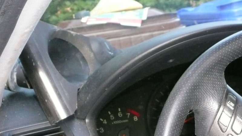
There's a square waveguide for sale which has an oblate spheroidal curve. You're trading one problem for another, but it's out there. Would be a heck of a lot easier than making a mold.
I've taken some pictures of it next to my mold, and posted them. (My mold is elliptical oblate spheroidal, and works very well. Better than anything else I've used. Must be something to this oblate spheroidal business 🙂 )
I think the concept of using the windshield is very good. All the data I have posted are using dome drivers. If you look at the effective radiation area of the compression drivers, it seems very close to the area of the throat. You can still do a different throat design such that a phase plug is not necessary. The only thing is directivity requirements would be very different for speaker spacing to listening distance ratio in a car.I gave up on using domes in waveguides a few years ago, but I think I'm ready to take another crack at it. I personally believe that a compression driver is a better solution, but I have a unique problem, and I can't find a way to solve it that doesn't involve a dome tweeter. Here's the situation:
I've built a ton of horns and waveguides, primarily for automotive use. When I first started, I built them full size. We're talking huuuge ol' horns that make the car basically undrivable. This is back in the 90s. As I began building waveguides, I found that you could use boundaries to extend the waveguide. And I don't mean an inch or two. I'm talking about removing over 75% of the waveguide.
Here's the problem I'm running in to: The size of the compression driver itself is really becoming an issue. I can't find compression drivers small enough to fit into corners. The best solution that I've found so far is to bend the throat of the waveguide, so that the compression driver enters at a 45 degree angle. But it's tricky, because the bend creates a dip in the frequency response, and the dip gets deeper as the bend gets bigger. (IE, if the compression driver enters the waveguide at a ninety degree angle you get a big fat dip due to a reflection off the wall of the waveguide.)
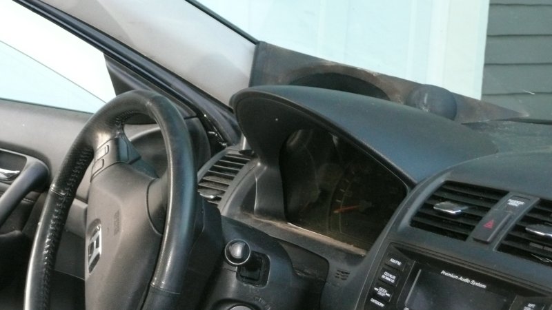
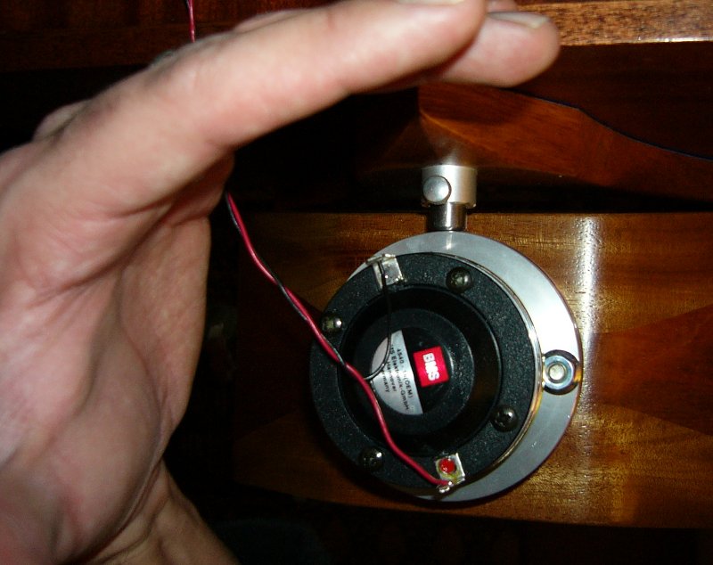
Here's the best waveguide I've built. It's an elliptical oblate spheroidal loaded by a BMS 4540ND. It has a horizontal coverage of 108 degrees, vertical of 72, and an average of 90. You can see that the compression driver enters at an angle. This allows me to push it as far back as possible on the dash of my car, which better mates with the angle of the dash and the windshield.
So here's what I'm thinking. If you a neodymium tweeter at the apex of a waveguide instead of a compression driver, you can push that waveguide almost all the way back. By pushing it back further, you can reduce the mouth of the waveguide even further. Basically, you let the windshield and the dash do more of the work.An externally hosted image should be here but it was not working when we last tested it.
Again, not saying that this is a good solution for the home, where depth isn't a problem. But my application is rather unique, and I simply can't think of another way to solve this.
By using a dome tweeter I will lose a great deal of efficiency, reduce power handling, and increase distortion. On the upside, it's smaller, looks better, and costs less. I have a hunch that a phase plug could be built to improve the high frequency polar response. Basically get the dome to behave more like a compression driver, and less like a dome.
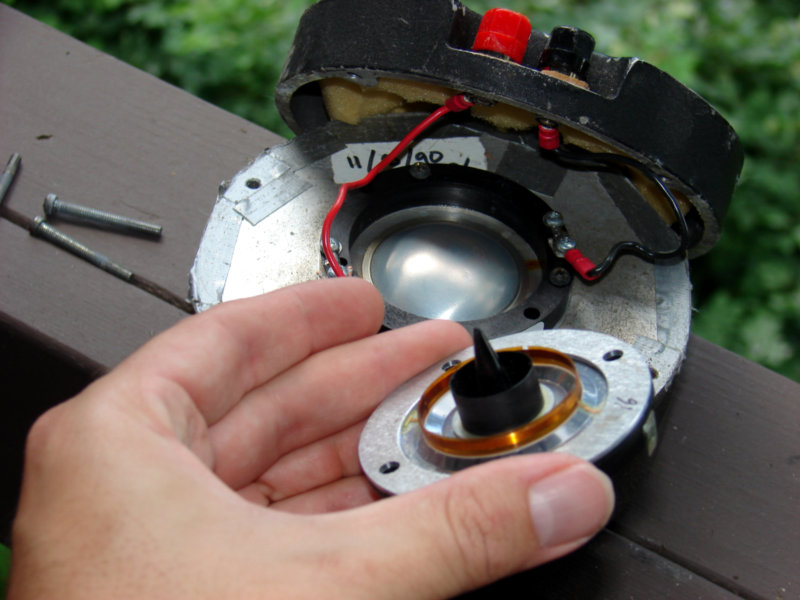
As I see it, a compression driver is a big dome tweeter with an extraordinarily powerful motor, and a carefully designed phase plug. Here are two compression drivers that I've used. JBL 2470 on the left, back when I was into huge horns in the car. BMS 4540ND in my hand, once I switched to Unity horns.
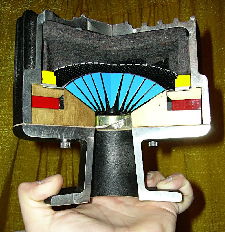
Here's a TAD compression driver cut in half. They had this laying around their demo room when I was there, a rather amazing paperweight if you ask me. In the cross section you can see that this isn't much different than a dome tweeter, except they've added a very carefully designed phase plug in front of the diaphragm, and the dome is inverted.
To give you a sense of scale, here's the compression driver that I'm using in my car, mounted on a conventional horn. (woodhorn.com btw.) You can see that the TAD absolutely dwarfs it.
Here's a pic of JBL's top of the line components, which use a waveguide that looks suspiciously like an elliptical oblate spheroidal. My design would be similar to this, but using the windshield to bring the soundstage to eye level, and to extend the curve of the waveguide. (In other words, my waveguides will have a narrower coverage angle than JBL's.)
So I would end up with a waveguide that uses the oblate spheroidal curve, but with a footprint that's about 75% smaller than the waveguides I am already using. I haven't decided yet if it will be a Unity. There *is* enough room to mount a couple of midranges to extend the response. The primary goal will be to reduce the waveguides size to the smallest footprint possible, and use the existing boundaries to extend the curve.
Anyone care to comment on these plans?
This is interesting. I have not seen what others refer to as on-axis dip in any of my sims and builds elliptic or circular.The only WG simulation tools I have available are Axi-Driver and Hornresp. In other words, I can sim only round WGs.
Any opinions on whether a 6:5 H:V aspect elliptical mouth would be enough to break up the on-axis dip apparently inherent in axi-symmetric waveguides? If not, what ratio would do the job? I would like to make the aspect ratio as tight as possible, but eliminating the dip has priority over aspect ratio.
Last edited:
I gave up on using domes in waveguides a few years ago, but I think I'm ready to take another crack at it. I personally believe that a compression driver is a better solution, but I have a unique problem, and I can't find a way to solve it that doesn't involve a dome tweeter.
....
Anyone care to comment on these plans?
Have you ever considered to use an AMT for your horns?
They already deliver a plain wave front - no small advantage if you are feeding horns.
Sure - they all are all basically rectangular - but would that bother you ?
Michael
I'm not sure you can NOT do the elliptical version. Not because it will necessarily result in a markedly superior product, but rather to maintain a competitive advantage.
I'm not sure about the competitive advantage. Most horn manufacturers did and do produce far more complex designs. But if the elliptical waveguide delivers better results (and I see them popping up everywhere) than the current one then it's a logical evolution in the Geddes design philosophy.
The final product (with a 15" midbass) will be superior to the current line but smaller than the Summa: that's where I would set the price point.
But in the end it's not about how high your tooling costs are or what IP is worth, people need to be willing to pay what you charge. Asking DIYers about pricing is like talking to a wall and expecting an answer.
Best, Markus
My circular horns have a similar on axis dip FWIW. It goes away fast off axis.This is interesting. I have not seen what others refer to as on-axis dip in any of my sims and builds elliptic or circular.
Dan
Some of my sims not posted did suggest that constant radius lip might result in on-axis dip FWIW.My circular horns have a similar on axis dip FWIW. It goes away fast off axis.
Dan
”For a relatively large object with such a complex shape AND considering small production runs requiring low cost/minimal labor there really is only one solution I can think of: Thermoforming.”
“…let the windshield and the dash do more of the work.”
Reading these so soon ion succession made me think of glassblowing.
“…let the windshield and the dash do more of the work.”
Reading these so soon ion succession made me think of glassblowing.
Member
Joined 2003
The only WG simulation tools I have available are Axi-Driver and Hornresp. In other words, I can sim only round WGs.
Any opinions on whether a 6:5 H:V aspect elliptical mouth would be enough to break up the on-axis dip apparently inherent in axi-symmetric waveguides? If not, what ratio would do the job? I would like to make the aspect ratio as tight as possible, but eliminating the dip has priority over aspect ratio.
Earl - Robert
Any thoughts on this question? Since my understanding of math at this level wouldn't fill a thimble, I would really appreciate your input, even if you don't have a definitive answer.
Earl - Robert
Any thoughts on this question? Since my understanding of math at this level wouldn't fill a thimble, I would really appreciate your input, even if you don't have a definitive answer.
Its a difficult question.
First, the axial dip will only occur when there are very low HOM and a highly coherent wavefront at the mouth. If the wavefront is not very close to purely spherical, then the precise phase cancellation right on axis will be blurred and not readily apparent. This is why it is seen in my waveguides and not a lot of other ones.
Assuming that everything else is done correctly and the mouth has a very accurate spherical wavefront, I really don't know how much of a purturbation from round is required to break up the axial hole. The answer is certainly going to be a matter of degrees. The less eccentic the mouth the greater the hole.
But size is also a factor since certain sizes exhibit a greater hole than others. This is because there is a resonance across the waveguide mouth that results from the diffraction at the edges. If this resonance is at the same frequency as the hole, then the hole will get deeper. If not then it will be shallower. This can be very hard to predict, but becomes clear after looking at scores of waveguide polar plots of different sizes, etc.
Member
Joined 2003
Thanks Earl. I hadn't thought of it as a gradual change...duh!
This is my starting point. You can see an on-axis dip of about 4db centered around 5k...the dip decreases to about 2db at 10 degrees off-axis and is completely gone before 20 degrees.
The WG is 30" OD x 12" deep, 1.4" entry, OS with a 10 degree overall entry angle, mouth "roundover" is a prolate section (not a constant radius). Measurement is 0, 10, 20, 30, 40 degrees from 4 meters.
Does this provide any clues on the amount of asymmetry needed? I don't picture myself building "scores" of molds since it took me weeks to get something usable for the first set of WGs.
This is my starting point. You can see an on-axis dip of about 4db centered around 5k...the dip decreases to about 2db at 10 degrees off-axis and is completely gone before 20 degrees.
The WG is 30" OD x 12" deep, 1.4" entry, OS with a 10 degree overall entry angle, mouth "roundover" is a prolate section (not a constant radius). Measurement is 0, 10, 20, 30, 40 degrees from 4 meters.
Does this provide any clues on the amount of asymmetry needed? I don't picture myself building "scores" of molds since it took me weeks to get something usable for the first set of WGs
.Does this provide any clues on the amount of asymmetry needed? I don't picture myself building "scores" of molds since it took me weeks to get something usable for the first set of WGs
No, I really don't have a clue, but a better scale on your plots would help - 50 dB vertical instead of 90 and 200 - 20 kHz instead of 20 - 20 k
Easiest would be to simply change the mouth flare rather than the whole device. Its the mouth that causes the problem not the waveguide. Varry the flare radius all the way arround would "change" the dip - probably better (?) but no idea how much.
- Home
- Loudspeakers
- Multi-Way
- Geddes on Waveguides