I would like to provide an answer to this question which was staring me in the face for some time. But Dr. Geddes might think my tone to be too authoritave so I'll wait any see if you get any other answers. I have asked very similar questions earlier without any response.😀tinitus said:Allow me a stupid question, but I dont understand this HOM when no one seems to have done any measurements to show its behaviour
How can you know the OS is superiour regarding HOM, is it by mathematical proove
Still, the OS also needs a foamplug
To me it sounds more like a matter of precise design of throath and curved mouth, which should be of benefit to any waveguide, and as I recall you have said so yourself
Its not dissbelief in any way and I dont mean to sound harsh ... only curious
soongsc said:
I would like to provide an answer to this question which was staring me in the face for some time. But Dr. Geddes might think my tone to be too authoritave so I'll wait any see if you get any other answers. I have asked very similar questions earlier without any response.😀
I'm interested in anything that you have to say if you don't claim things that you are guessing at as facts.
poptart said:Bratislav, maybe I wasn't clear or I'm not reading you right but I think we're agreeing.
It's my understanding that:
Stiffer = faster
denser = slower
and it's the balance of these two effects that determines the speed. The density of water would make the speed of sound slower than air if it weren't for the greatly increased stiffness that more than makes up for that.
OK, I misread you (I think it was just me being dense == slow
😀 )
gedlee said:
The size would have to grow to an enormous device to do what you want.
First to control directivity to 600 Hz would require a mouth that is about 30" across. Then to load down to this frequency - assuming the driver can go this low, which I doubt, would require a narrower angle, say 60°. Now the length of this device has just quadrupled from the one that I use. Good luck with making and using that. And what are you going to cross over to at 600 Hz that has a polar response of only 60°? A 27" woofer?
Narrower angles improve loading at LF and reduce the HOM, but cause massive growth in size as highlighted above. The reason that I use what I use is not a coincidence. Things simply get out of hand quickly taking the design in different directions without making major compromises in performance.
Dr. Geddes,
I wanted to revisit this reply from you and make sure I understand it correctly. Is it correct that a more narrow angle oblate spheriod wave guide (i.e. 60 degrees) does not generate more HOMs than a wider angle oblate spheriod wave guide (i.e. 90 degree)? In addition, is there a practical limit to how narrow an angle of wave guide one should attempt? For example, it would appear to be impractical to construct a 20 degree oblate spheroid wave guide and expect it to sound good. Then again I don’t know. That’s why I’m asking. Thanks.
Rgs, JLH
You still need to match the woofer and wg directivity at the crossover. A smaller angle leads to a higher crossover point or a bigger woofer.
I also favour the idea of a small coverage angle, for the "headphone" sound. But its hard to realize, since your woofer is nearly as big as it can be, so you have to raise the crossover point, which means that the frequency area that has constant directivity gets smaller - lots of tradeoffs for the smaller angle.
I also favour the idea of a small coverage angle, for the "headphone" sound. But its hard to realize, since your woofer is nearly as big as it can be, so you have to raise the crossover point, which means that the frequency area that has constant directivity gets smaller - lots of tradeoffs for the smaller angle.
JLH said:
Dr. Geddes,
I wanted to revisit this reply from you and make sure I understand it correctly. Is it correct that a more narrow angle oblate spheriod wave guide (i.e. 60 degrees) does not generate more HOMs than a wider angle oblate spheriod wave guide (i.e. 90 degree)? In addition, is there a practical limit to how narrow an angle of wave guide one should attempt? For example, it would appear to be impractical to construct a 20 degree oblate spheroid wave guide and expect it to sound good. Then again I don’t know. That’s why I’m asking. Thanks.
Rgs, JLH
In reading what Earl has posted and written, it would appear that your conclusion is partially correct. A 20 degree, conic, OS horn would of course not have a lot of curvature at the throat, as the waveshape required is closer to that of a plane wave than say a 90 degree conic.
The complication with smaller angles is one of dimension and depth if you wish to maintain the pattern over the same bandwidth as the 90 degree waveguide. You now need a mouth dimension of 4.5x the 90 degree waveguide if you wanted the same degree of pattern control.
Next, you have the problem of the larger angle difference between the 20 degree conic and a flat baffle. This requires an even larger radius, as you effectively shift the diffraction problems from the throat to the mouth termination.
Finally you have the added complication of integrating this narrow pattern with a lower-frequency device which will have even greater source separation due to the required, larger mouth dimension.
Of course Earl will likely have more to add or correct, but those should be some obvious reasons to carefully re-consider why a 20 degree horn might be desired for home use. In very large venues obviously needs and uses are different.
JLH said:
Dr. Geddes,
I wanted to revisit this reply from you and make sure I understand it correctly. Is it correct that a more narrow angle oblate spheriod wave guide (i.e. 60 degrees) does not generate more HOMs than a wider angle oblate spheriod wave guide (i.e. 90 degree)? In addition, is there a practical limit to how narrow an angle of wave guide one should attempt? For example, it would appear to be impractical to construct a 20 degree oblate spheroid wave guide and expect it to sound good. Then again I don’t know. That’s why I’m asking. Thanks.
Rgs, JLH
The HOMs have higher "cut-in" frequencies with narrower angles and hence within the audio bandwidth, for a give throat size, as the angle decreses the HOM content decreases. But Mark is correct, building such a device is impractical. For a miriad of reasons 45° seems to be a sort of optimal angle.
I too thanks the moderators as I was tiring of the water discussion.
MaVo said:You still need to match the woofer and wg directivity at the crossover. A smaller angle leads to a higher crossover point or a bigger woofer.
I also favour the idea of a small coverage angle, for the "headphone" sound. But its hard to realize, since your woofer is nearly as big as it can be, so you have to raise the crossover point, which means that the frequency area that has constant directivity gets smaller - lots of tradeoffs for the smaller angle.
I should have stated this before, my bad. I'm not matching to a direct radiator. I'm matching to a mid-bass horn.
Rgs, JLH
That doesn't make the problem any easier, it just moves it lower in frequency.
Personally I don't like the headphone sound, it does make me feel like there is a musical presence in the room.
Personally I don't like the headphone sound, it does make me feel like there is a musical presence in the room.
I was invited to listen to a pair of speakers with a horn supposedly handling 800Hz and up. It sounded terrible, and I did not have the heart to voice it from an engineering point of view, but rather commented it had a tube sound even though driven by solid state amps. Not really sure whether it was the driver or the horn.
I am interested in trying a car dash mount size elliptic wave guide with a direct radiating driver, possibly with an inverted dome. Although this is not the best configuration, but it certainly seems like a good low cost candidate. If the results sound better than the horns I have heard so far, then I will take a bigger step.
I am interested in trying a car dash mount size elliptic wave guide with a direct radiating driver, possibly with an inverted dome. Although this is not the best configuration, but it certainly seems like a good low cost candidate. If the results sound better than the horns I have heard so far, then I will take a bigger step.
I recall reading in the Richard Morgan paper that the cut-on frequency for HOMs is ((1.84 X C)/(2 X Pi X a))
"Propagating higher order modes" 2.2.3
According to my calculations a 1" compression driver would be expected to generate HOMs above 7.9KHz. In addition, a 1.4" compression driver would be expected to generate HOMs above 5.65KHz. Lastly, a 2" compression driver would be expected to generate HOMs above 3.95KHz.
Do we also need to take into consideration the mouth radius and calculate possible HOMs caused by it? If this is the case, then I can begin to see why it is important to treat the mouth termination with great care. So, mouth termination should be something along the lines of 1/4 WL of the lowest frequency of interest then?
Rgs, JLH
Could you please post a link to this paper (if it is freely available)?
Interesting for me is, that according to this equation, a unity like hornspeaker with midranges driving the same horn as the compression driver, should have its first midrange HOM around 3-3.5 khz - a frequency far out of the midrange passband.
Interesting for me is, that according to this equation, a unity like hornspeaker with midranges driving the same horn as the compression driver, should have its first midrange HOM around 3-3.5 khz - a frequency far out of the midrange passband.
JLH said:I recall reading in the Richard Morgan paper that the cut-on frequency for HOMs is ((1.84 X C)/(2 X Pi X a))
Rgs, JLH
This equation cannot possibly be correct because it is too simple. The cut-in frequency depends on angle and there is no angle parameter. It is about correct for a 1" throat at 45° for the lowest axi-symmetric mode. Non-axi-symmetric modes cut-in a lot lower.
And regarding the unity horn, the HOM for the midranges has never been what worried me. What I was concerned with was the diffraction/scattering of the compression driver off of the midrange helmholtz resonators. This could be quite significant.
I have done a lot of this midrange into the sides of the waveguide thing in line arrays and its seldom the midrange that sees the problem, its the compression driver. These resonators at the sides could cause a lot of wavefront distortion resulting in HOMs. I have no data either way - I'm looking forward to some from Tom - but based on my experince in the past this will be a problem. To what extent is TBD.
gedlee said:...He [Don Keele] was tell me that when they rotated the driver on a waveguide they got a different polar pattern! Thats when I came to realize that real devices were anything but ideal.
It would be of great interest to me to study where these asymmetries come from. Alas, nobody does advanced work like this anymore.
I would guess that the difference might be because the positions of the phase plug slots could be at different angles when the driver is rotated. If the slots were indexed so they fell at the same angular position no matter how the driver was mounted, the polars may not have changed when the driver was rotated.
It would be interesting to see. Maybe plug one of the slits and watch what happens, or use a different driver with a different phase plug to see the difference.
One thing that makes it appear as though the phase plug slots are responsible are the relative positions of the "hot" and "cold spots on the two horns. Notice below that they stay in approximately the same position on each horn. The amplitudes change, but the positions remain the same.
Attachments
Interesting observation, which implies the asymmetry is coming from the driver, but where else COULD it come from.
A compression driver and a horn. Looks comprehensible enough. But its an abyss. Compression drivers must undergo serious overhaul so to do justice to new waveguide knowledge IMHO. Only if the industry was interested enough...
You are correct that the industry is way behind in compression driver design for improved waveguides. And they don't seem interested in changing.
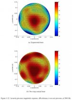
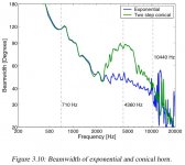
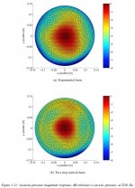
I just discovered many of the pictures in the Morgans thesis have reversed captions - the two-step conical horn is shown in Fig. 3.10 to have wider dispersion 2.2 ~ 11 kHz region compared to the exponential, as you would expect. However, that's not what the 2D graphs show, where many figures (including those in the Appendix) show the widest dispersion coming from the exponential horn. Compare Figure 3.10 to the 2D figures and you will see what I mean.
Having written and edited manuals for many years, I know from experience how common it is to get pictures, captions, and text references mixed up. It is a lot more common in technical publications than people realize, since the folks doing the artwork are not usually the writers - and it takes a very careful editorial eye to catch these errors.
Having written and edited manuals for many years, I know from experience how common it is to get pictures, captions, and text references mixed up. It is a lot more common in technical publications than people realize, since the folks doing the artwork are not usually the writers - and it takes a very careful editorial eye to catch these errors.
Attachments
- Home
- Loudspeakers
- Multi-Way
- Geddes on Waveguides