Yes, I saw that over at the other thread. Its a good loudspeaker no doubt. Much like I have been making for ten years now. Measures - to the extent that we can tell, very much like my speakers. A more detailed polar map would be instructive instead of the "averaged" curves that they show.
Do you know the price?
What else did you expect Sean to say? He took a real beating over at Linked-in for his participation in Harman's movie about audio quality. The consensus was that it was poorly done, over hyped, inaccurate and misleading and that Sean, especially as Pres. of the AES, should not have been involved with it. It was not up to his usual quality work.
Last edited:
Antithesis
Street price is about $6,000 each, sans amplifiers & crossovers.
Only replication of the horn design makes a DIY copy difficult.
Wide dispersion seems the be due to total wave front chaos induced by an 'aggressive' horn throat geometry.
This design approach would appear to be the antithesis of that of an OS horn.
Regards,
WHG
Yes, I saw that over at the other thread. Its a good loudspeaker no doubt. Much like I have been making for ten years now. Measures - to the extent that we can tell, very much like my speakers. A more detailed polar map would be instructive instead of the "averaged" curves that they show.
Do you know the price?
What else did you expect Sean to say? He took a real beating over at Linked-in for his participation in Harman's movie about audio quality. The consensus was that it was poorly done, over hyped, inaccurate and misleading and that Sean, especially as Pres. of the AES, should not have been involved with it. It was not up to his usual quality work.
Street price is about $6,000 each, sans amplifiers & crossovers.
Only replication of the horn design makes a DIY copy difficult.
Wide dispersion seems the be due to total wave front chaos induced by an 'aggressive' horn throat geometry.
This design approach would appear to be the antithesis of that of an OS horn.
Regards,
WHG
Last edited:
These M2 horns look like some "tits" over the RCA LC1 speaker membrane?
I dont like them visually... sorry
.
For measuring and experimenting may not bad idea to have clay model fixed on the stand.
So it will allow modeling the shape.
.
this example of horn shape I send pics of cross section, is as I am remembered 108 deg
coverage angle. Maybe I will put it lower, making the horn little longer. I dont know at the moment.
This design approach would appear to be the antithesis of that of an OS horn.
That appears to be true and may have been the goal.
Member
Joined 2003
Wide dispersion seems the be due to total wave front chaos induced by an 'aggressive' horn throat geometry.
Can you say more about the wave front chaos and any audible consequences?
SWAG for Now
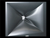
First, a brief description of the horn geometry:
The horn throat is formed by cylinder with (4) V-shaped notches cut into its end forming two horizontal points that are bent inward towards the horn axis and two (vertical) points that are simply rounded off. JBL product engineering staff collectively call these prominences, "knuckles". This profile is then extended outward in a radial fashion to form the horn body consisting of for expanding convex 'cheeks' bounded by diagonal 'trenches'.
Second, an attempt to describe the diffraction process that accounts for the wide dispersion:
At any given instant only a portion of the outbound wave front escapes the cylinder to be diffracted over the knuckle (slot) edges and allowed to travel down the trenches. This geometry accounts for the wide dispersion characteristic exhibited by the horn up to and above 10kHz. However, as part of the diffraction process, back-waves are most certainly being generated that travel back down into the compression chamber passages and collide with outbound waves. JBL claims that horn geometry sufficiently mitigates the attendant interference (chaos) that is occurring there.
At this time, I have not been able to obtain design details beyond those provided earlier in this thread. I suspect, the response ripple will be hidden by the 'smoothing' of any graph published by JBL.
Of the few owner reviews I have read, none have been negative (all raves); but again, what owner is going to admit that the performance of his/her $12,000 loudspeaker purchase was less than stellar?
Regards,
WHG
Can you say more about the wave front chaos and any audible consequences?
First, a brief description of the horn geometry:
The horn throat is formed by cylinder with (4) V-shaped notches cut into its end forming two horizontal points that are bent inward towards the horn axis and two (vertical) points that are simply rounded off. JBL product engineering staff collectively call these prominences, "knuckles". This profile is then extended outward in a radial fashion to form the horn body consisting of for expanding convex 'cheeks' bounded by diagonal 'trenches'.
Second, an attempt to describe the diffraction process that accounts for the wide dispersion:
At any given instant only a portion of the outbound wave front escapes the cylinder to be diffracted over the knuckle (slot) edges and allowed to travel down the trenches. This geometry accounts for the wide dispersion characteristic exhibited by the horn up to and above 10kHz. However, as part of the diffraction process, back-waves are most certainly being generated that travel back down into the compression chamber passages and collide with outbound waves. JBL claims that horn geometry sufficiently mitigates the attendant interference (chaos) that is occurring there.
At this time, I have not been able to obtain design details beyond those provided earlier in this thread. I suspect, the response ripple will be hidden by the 'smoothing' of any graph published by JBL.
Of the few owner reviews I have read, none have been negative (all raves); but again, what owner is going to admit that the performance of his/her $12,000 loudspeaker purchase was less than stellar?
Regards,
WHG
Attachments
Last edited:
First, a brief description of the horn geometry:
The horn throat is formed by cylinder with (4) V-shaped notches cut into its end forming two horizontal points that are bent inward towards the horn axis and two (vertical) points that are simply rounded off. JBL product engineering staff collectively call these prominences, "knuckles". This profile is then extended outward in a radial fashion to form the horn body consisting of for expanding convex 'cheeks' bounded by diagonal 'trenches'.
Second, an attempt to describe the diffraction process that accounts for the wide dispersion:
At any given instant only a portion of the outbound wave front escapes the cylinder to be diffracted over the knuckle (slot) edges and allowed to travel down the trenches. This geometry accounts for the wide dispersion characteristic exhibited by the horn up to and above 10kHz. However, as part of the diffraction process, back-waves are most certainly being generated that travel back down into the compression chamber passages and collide with outbound waves. J...........
At this time, I have not been able to obtain design details beyond those provided earlier in this thread. I suspect, the response ripple will be hidden by the 'smoothing' of any graph published by JBL.
......
WHG
Hi whgeiger,
Thank You for the very nice explanation about M2 horn.
All of that remind me of KARLSON COUPLER, or Karslon-Tube,
but on M2 throat it seams that applied 4 of Karlson V-shape slots
KKoppler
http://home.planet.nl/~ulfman/files/poppe_kcoupler.pdf
mostly applicable to hi-frequency region.
Talking about the ripple may be some data about DSP equalized data (as an 'inverse') can be get
JBL Master Reference Monitor - Page 34
Reagrds
ivica
Last edited:
However, as part of the diffraction process, back-waves are most certainly being generated that travel back down into the compression chamber passages and collide with outbound waves. JBL claims that horn geometry sufficiently mitigates the attendant interference (chaos) that is occurring there.
Hello whgieger
Well there is no cylindrical cavity in front of the throat. At least I don't see one. The 4 channels go all the way to the throat. Without a uniform conduit back into the throat how are the reflections going to get back there in a uniform manner. The way I see it the channels act to break things up and randomize the reflections back down the throat. It is also a very rapid flare rate which is also going to help matters.
Just floating this out there, what do you think??
Rob🙂
Prophetic
Ivica,
Thanks for the informative references. In particular, the conclusions [1] presented in the first of these and repeated here. I wonder whether Sprinkle came across this gem during his studies, or whether it was just serendipity-rediscovery.
Regards,
Bill
[1] CONCLUSIONS
"Many aspects of the K-coupler have not yet been thoroughly investigated. It should be apparent, how¬ever, that the configuration presented herein is only one of many possible configurations. For instance, the designer could tailor the tapered opening to fit specific needs, e.g., parts may be formed with a series of slits, or the width of the opening may be varied in any number of ways."
"Thus far, nothing has been mentioned concerning the dispersion characteristics or efficiency of the K-coupler. While these characteristics were not measured on the laboratory model, experience with loudspeaker systems designed using this principle in a somewhat more com¬plicated structure has demonstrated that uniform dis¬persion over a solid angle of 120° is not unusual even at high frequencies and that efficient loudspeakers provide overall system efficiencies of 20 to 50 percent. Further information on the design of acoustical devices employ-ing the K-coupler will appear in a forthcoming paper."
Martin C. Poppe, Jr.
IEEE Transactions, Vol AU-14, No. 4, pp. 163-167 (Dec-1966)
Hi whgeiger,
Thank You for the very nice explanation about M2 horn.
All of that remind me of KARLSON COUPLER, or Karslon-Tube,
but on M2 throat it seams that applied 4 of Karlson V-shape slots
KKoppler
http://home.planet.nl/~ulfman/files/poppe_kcoupler.pdf
mostly applicable to hi-frequency region.
Talking about the ripple may be some data about DSP equalized data (as an 'inverse') can be get
JBL Master Reference Monitor - Page 34
Reagrds
ivica
Ivica,
Thanks for the informative references. In particular, the conclusions [1] presented in the first of these and repeated here. I wonder whether Sprinkle came across this gem during his studies, or whether it was just serendipity-rediscovery.
Regards,
Bill
[1] CONCLUSIONS
"Many aspects of the K-coupler have not yet been thoroughly investigated. It should be apparent, how¬ever, that the configuration presented herein is only one of many possible configurations. For instance, the designer could tailor the tapered opening to fit specific needs, e.g., parts may be formed with a series of slits, or the width of the opening may be varied in any number of ways."
"Thus far, nothing has been mentioned concerning the dispersion characteristics or efficiency of the K-coupler. While these characteristics were not measured on the laboratory model, experience with loudspeaker systems designed using this principle in a somewhat more com¬plicated structure has demonstrated that uniform dis¬persion over a solid angle of 120° is not unusual even at high frequencies and that efficient loudspeakers provide overall system efficiencies of 20 to 50 percent. Further information on the design of acoustical devices employ-ing the K-coupler will appear in a forthcoming paper."
Martin C. Poppe, Jr.
IEEE Transactions, Vol AU-14, No. 4, pp. 163-167 (Dec-1966)
More Choas
Rob,
We must be looking at different pictures of the same horn. The throat is cylindrical with exception of the horizontal knuckle intrusions ("points bent inward") as described before. The rest embellishes, the albeit brief description provided. The geometric portion simply provides a scaffold to further describe what is going on here acoustically. I minimized my comments here because they represent nothing more than a SWAG as characterized before.
Only the designer Sprinkle, witness to the lab data, knows for sure.
Regards,
Bill
Hello whgieger
Well there is no cylindrical cavity in front of the throat. At least I don't see one. The 4 channels go all the way to the throat. Without a uniform conduit back into the throat how are the reflections going to get back there in a uniform manner. The way I see it the channels act to break things up and randomize the reflections back down the throat. It is also a very rapid flare rate which is also going to help matters.
Just floating this out there, what do you think??
Rob🙂
Rob,
We must be looking at different pictures of the same horn. The throat is cylindrical with exception of the horizontal knuckle intrusions ("points bent inward") as described before. The rest embellishes, the albeit brief description provided. The geometric portion simply provides a scaffold to further describe what is going on here acoustically. I minimized my comments here because they represent nothing more than a SWAG as characterized before.
Only the designer Sprinkle, witness to the lab data, knows for sure.
Regards,
Bill
The only "idea" that I can see behind the JBL device is that if enough diffraction aspects can be created then the net effects of these will be smoothed out simply by summing over all of them in the far field. I can see that there could be some merit to this concept.
For example, in my device the wavefront is extremely coherent. This means that when this wave gets diffracted at the mouth the diffraction is also extremely coherent. This causes a hole on axis. I know that if I were to randomly modulate the mouth edge that this hole would get smoothed away. One could take this same concept right down to a diffraction slit. But rather than a "random" situation, enough "regular" diffractions of various kinds are created to create the same net effect. The end result looks "cool", is patentable and no one needs to know that a random design just might work as well. It looks carefully implemented, as if each facet had a function, and they do, just not a coherent one. The idea is to smear the results.
Audibility, that's anyone's guess. SWAG away.
My SWAG - a lot of smaller randomized diffractions would be less audible than a single one of the same net power. But it could be more audible than a single one of less power. That's the $64,000 question.
Ivica,
Thanks for the informative references. In particular, the conclusions [1] presented in the first of these and repeated here. I wonder whether Sprinkle came across this gem during his studies, or whether it was just serendipity-rediscovery.
Regards,
Bill
[1] CONCLUSIONS
"Many aspects of the K-coupler have not yet been thoroughly investigated. It should be apparent, however, that the configuration presented herein is only one of many possible configurations. For instance, the designer could tailor the tapered opening to fit specific needs, e.g., parts may be formed with a series of slits, or the width of the opening may be varied in any number of ways."
"Thus far, nothing has been mentioned concerning the dispersion characteristics or efficiency of the K-coupler. While these characteristics were not measured on the laboratory model, experience with loudspeaker systems designed using this principle in a somewhat more complicated structure has demonstrated that uniform dispersion over a solid angle of 120° is not unusual even at high frequencies and that efficient loudspeakers provide overall system efficiencies of 20 to 50 percent. Further information on the design of acoustical devices employing the K-coupler will appear in a forthcoming paper." .....
Martin C. Poppe, Jr.
IEEE Transactions, Vol AU-14, No. 4, pp. 163-167 (Dec-1966)
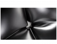
Hi whgeiger,
Looking at the figures You have send us in the:
http://www.diyaudio.com/forums/multi-way/103872-geddes-waveguides-709.html#post4052427
especially the second one, mentioned V-shape slits, as I have said reminded me of K-coupler, and if the height of the slit is about 1.5 inch, that would correspond to the frequency from the 2300Hz and up, expected over 20kHz, but from the M2 figures it seems to me that there are present another 4 K-coupler perpendicular to the horn axis whose slits are "looking towards" the listeners, or these graves behave as some kind of reflectors....
May one vertical slit K-coupler is coupled with the horizontal one K-coupler , totally 4 pairs positioned on the horn diagonals.
Unfortunately all of that is just "guessing"
Regards
Ivica
Chaos Revisited
No such SWAG has been made here, only a comment on M2 owner motivation has been provided.
Most likely, any such audible artifacts are being masked by signal conditioning in the DSP crossover that is used here. This tack is not a new one for driving CD horns.
Regards,
WHG
The only "idea" that I can see behind the JBL device is that if enough diffraction aspects can be created then the net effects of these will be smoothed out simply by summing over all of them in the far field. I can see that there could be some merit to this concept.
For example, in my device the wavefront is extremely coherent. This means that when this wave gets diffracted at the mouth the diffraction is also extremely coherent. This causes a hole on axis. I know that if I were to randomly modulate the mouth edge that this hole would get smoothed away. One could take this same concept right down to a diffraction slit. But rather than a "random" situation, enough "regular" diffractions of various kinds are created to create the same net effect. The end result looks "cool", is patentable and no one needs to know that a random design just might work as well. It looks carefully implemented, as if each facet had a function, and they do, just not a coherent one. The idea is to smear the results.
Audibility, that's anyone's guess. SWAG away.
No such SWAG has been made here, only a comment on M2 owner motivation has been provided.
My SWAG - a lot of smaller randomized diffractions would be less audible than a single one of the same net power. But it could be more audible than a single one of less power. That's the $64,000 question.
Most likely, any such audible artifacts are being masked by signal conditioning in the DSP crossover that is used here. This tack is not a new one for driving CD horns.
Regards,
WHG
Last edited:
Hi whgeiger,
>snip<
Unfortunately all of that is just "guessing"
Regards
Ivica[/QUOTE]
Hi Ivica,
The patent (application) should reveal the details, but I have not been able to find it. Apparently, Sprinkle is not the inventor and Harman is not the assignee.
Regards,
Bill
Hi Ivica,
The patent (application) should reveal the details, but I have not been able to find it. Apparently, Sprinkle is not the inventor and Harman is not the assignee.
Regards,
Bill
Harman International (or JBL) is not the assignee? That's unusual. It's hard to imagine any employee of Harman not having the patent assigned to their employer; that's a condition of employment at most companies. The practice goes back to Edison and even earlier.
Is Harman International paying royalties to someone else for the patent? That's even harder to imagine. The majority of hifi companies have an unwritten "Not Invented Here" policy and are very reluctant to pay money to outsiders.
Hmm ... maybe it's a design patent, not an invention. That would give (limited) protection from cosmetic copies. If Harman couldn't prove novelty, that would be the fallback position. But it seems like the US Patent Office will patent anything these days, so that's an unlikely scenario as well.
Last edited:
No such SWAG has been made here,
Regards,
WHG
I never said it was 🙄 I was inviting people to do so.
Trade Secrets, Maybe
Hi Lynn,
I looked at lists of Harmon applications for years 2009-2014, not there.
I did a search "in/Sprinkle" only two were surfaced, neither was for waveguides/horns.
Saving a search error, a patent application may have been withheld, due to the required disclosure. Reportedly, if you try to buy one of these horns as a repair part, you must send in the broken one first al la RMA style.
Regards,
Bill
Harman International (or JBL) is not the assignee? That's unusual. It's hard to imagine any employee of Harman not having the patent assigned to their employer; that's a condition of employment at most companies. The practice goes back to Edison and even earlier.
Is Harman International paying royalties to someone else for the patent? That's even harder to imagine. The majority of hifi companies have an unwritten "Not Invented Here" policy and are very reluctant to pay money to outsiders.
Hmm ... maybe it's a design patent, not an invention. That would give (limited) protection from cosmetic copies.
Hi Lynn,
I looked at lists of Harmon applications for years 2009-2014, not there.
I did a search "in/Sprinkle" only two were surfaced, neither was for waveguides/horns.
Saving a search error, a patent application may have been withheld, due to the required disclosure. Reportedly, if you try to buy one of these horns as a repair part, you must send in the broken one first al la RMA style.
Regards,
Bill
Lynn
Not filing a utility patent would make a lot of sense if one did not want to disclose how you thought it worked. For example, if this was developed strictly by cut-N'-try then it might be difficult to get anything meaningful patented. Or maybe they just want it as a trade secret, but that seems unlikely since then it would be easy to copy.
Are we sure that there is a patent?
Lynn
>snip<
Are we sure that there is a patent?
Earl,
No we are not sure. Harman claims application, but I cannot find it.
The audibility SWAG offer is a target for you to shoot at. I will take a pass on that invitation.
Regards,
Bill
I know that if I were to randomly modulate the mouth edge that this hole would get smoothed away. One could take this same concept right down to a diffraction slit. But rather than a "random" situation, enough "regular" diffractions of various kinds are created to create the same net effect. The end result looks "cool", is patentable and no one needs to know that a random design just might work as well. It looks carefully implemented, as if each facet had a function, and they do, just not a coherent one. The idea is to smear the results.
Audibility, that's anyone's guess. SWAG away.
My SWAG - a lot of smaller randomized diffractions would be less audible than a single one of the same net power. But it could be more audible than a single one of less power. That's the $64,000 question.
SWAG: Perhaps the wrinkled shape at the throat is intentionally designed to break up a planar wavefront, producing an incoherent wave by the time it emerges from the horn? Effectively, the horn analog of NHT's multiple-resonance transducer. As you mentioned, the exact opposite of a OSWG.
There's quite a lot of DSP in this system, which can smooth out the wrinkles, at least for the microphone's benefit.
Last edited:
- Home
- Loudspeakers
- Multi-Way
- Geddes on Waveguides