Augerpro's measurements, while the best I know of available, are far from complete. I should have mentioned, don't think Augerpro's comform to what I'm asking for.
I can't imagine that simulations in the break up region with natural fiber cones could be valid, but may be close with synthetic or metallic cones. What I've measured agrees with what Dr. Geddes states. I have some drivers with all metallic and synthetic materials. Maybe they'd prove more similar however. I need to make those measurements. Even then, statistics of 2 are not very significant. All of the paper cone drivers I've measured have been significantly different from one another.
Edit:
Tinnitis, I too have wondered about the cone mass thing--as too higher mass cones may be well behaved. Many damping compounds are very heavy by volume. The Summa uses a very heavy cone by 15" pro standards.
Dan
Last edited:
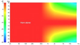
I think the important thing is to not cross so high that the woofer's pattern narrows and then the pattern widens again as the tweeter kicks in. These sims are based on the measured directivity of the QSC horn and the theoretical directivity of a 15" woofer (13" piston) and a hypothetical 1" piston. Both are crossed LR4 at 1300. The 15" is just starting to show a bit of wide-narrow-wide so 1300 is probably about as high as you'd wan't to go with that driver. But the 1" woofer shows a nice smooth transition. A too-big woofer or a too-high crossover isn't so good. A too-small woofer or a too-low crossover is no problem.Yes. If the directivities do not match then the polar response through the crossover will not be smooth, nor will the DI for any angle. This is a critical part of the design.
15" woofer
1" woofer
Attachments

Last edited:
Unfortunately those sims don't look much like actual measured data for a 15" woofer (see Summa at GedLee LLC under loudspeakers, the polar map program). And your conclusions don't seem right either. A 1" woofer vs. a 15" woofer!? Those sims don't look right at all. (Or maybe I don't understand what you are doing.)
I suppose mms/cone weight would be a factor too
I know of no reason why cone mass should affect directivity. Directivity is entirely a geometrical thing and has nothing to do with other mechanical parameters. Cone radius and depth is 95-99% of the result.
Edit: we are talking about non-modal breakup region here. Once the cone starts to break-up then the polar patern is as chaotic as the breakup modes - the driver isn't usable in that frequency region. Cone mass has an effect up very high, but not down lower where the cone is mostly a rigid mass. But even in nthe breakup region, its mostly geometry and cone stiffness that enters the problem. Mass isn't a big contributor.
Last edited:
Dan, I have posted in the measurement thread about augerpro's measurement requirements. Its a little off topic to this thread.
The Summa crosses much lower if I'm not mistaken and your 15" waveguide doesn't have the same polar response as the QSC horn. My point is that the cone size sets the upper limit of the XO frequency but not the lower limit. Cross way low and the woofer and tweeter still match in directivity -- neither has very much. You can still get a smooth transition as the horn/waveguide's directivity kicks in.Unfortunately those sims don't look much like actual measured data for a 15" woofer (see Summa at GedLee LLC under loudspeakers, the polar map program). And your conclusions don't seem right either. A 1" woofer vs. a 15" woofer!? Those sims don't look right at all. (Or maybe I don't understand what you are doing.)
Cross way low and the woofer and tweeter still match in directivity -- neither has very much. You can still get a smooth transition as the horn/waveguide's directivity kicks in.
If by this point you mean that both the woofer and tweeter are omnidirectional pattern, there is some truth to that, but not if any kind of directional response is desired. You will note that the 15" speaker in the Summa is not even approaching omni until about 400 Hz. You can't really take a tweeter that low. Basically, I just don't agree with your point, or, again, I don't get it. There is one and only one frequency at which a directional waveguide and the woofer match directivity. You either crossover at that frequency or you will not have an optimal situation.
Your sims are totally unrealistic. I'd use SPEAK if I were you, the results will be more like reality.
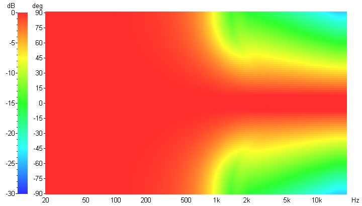
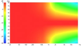
Maybe this will show it a bit better. Both of these have 15" woofers and the QSC horn. The first crosses at 1300 and the second crosses at 500, LR4 acoustic.
Now both presume that you can EQ the horn's response to LR4 acoustic and that's probably not possible at 500 with the QSC given its steep roll-off below 800. But I think the principle still stands.
Upper limit of XO frequency is determined by the cone diameter.
Lower limit of XO frequency is determined by where the horn/waveguide starts rolling off.
It may work out that matching directivity gives you the one and only best frequency but it may not. Consider a 10" woofer with a 15" waveguide. You could cross that considerably lower than where the directivities match and it would work just fine. It might even work better when you look at the big picture considering driver capabilities, vertical polars, etc.
1300 XO
500 XO
Attachments
Sorry Dennis, but I remain unconvinced. You are using sims that I have already shown aren't even close to reality to prove a point that I don't agree with. I have designed more than a few 2-way systems with waveguides and I'll tell you that they don't work anything like what you are suggesting.
Well, I didn't really expect to change your mind, Earl (has anyone ever?) 🙂 Plenty of designers around the world use LspCAD and find that it does a good job of predicting what they actually measure. I don't think it's a software problem.
Using your software and measurements, what happens if you use a 10" woofer and a 15" waveguide, crossed at the same frequency as the Summa (well below where the directivities match)?
Using your software and measurements, what happens if you use a 10" woofer and a 15" waveguide, crossed at the same frequency as the Summa (well below where the directivities match)?
........SNIP........
Edit: we are talking about non-modal breakup region here. Once the cone starts to break-up then the polar patern is as chaotic as the breakup modes - the driver isn't usable in that frequency region. Cone mass has an effect up very high, but not down lower where the cone is mostly a rigid mass. But even in nthe breakup region, its mostly geometry and cone stiffness that enters the problem. Mass isn't a big contributor.
That makes sense and is close to what I meant in my previous post though I was hoping the mass would play a greater roll. I'd sure like to see some data on the cone mass effects at high frequencies, but it's hard to add mass w/o effecting rigidity. IOW, isolating the variable of concern in an experiment wouldn't be easy, but there should be some simple applicable math for a theoretical demonstration. This is Physics 101 right? Any case I believe you are correct. So maybe it's just that more massive cones have a tendency to also be more rigid thus the Summa's woofer working well and thus I'll keep looking for answers.
Thanks,
Dan
Catapult, in your second set of comparisons I notice that the higher crossover (1300Hz) actually shows a more narrow dispersion between 1kHz and 2kHz.
Is this because the waveguide is rather small and the 15 inch woofer has narrow dispersion down lower? or is there some phase cancellation going on? or none of the above?
Is this because the waveguide is rather small and the 15 inch woofer has narrow dispersion down lower? or is there some phase cancellation going on? or none of the above?
Catapult, could you show the same plots with a steeper crossover slope? Something like 36dB/oct or more?
When using a smaller woofer you rely on the crossover slope to do the transission from the woofer directivity (omni if low enough) to the horn directivity (still controlled if not too low). So the steeper le slope the steeper the directivity transission. With brickwall FIR filter you really need to match directivity at the crossover point (but I think that is never really possible: even if you match the -6dB point you will have discontinuities somewhere).
So I would be curious to see your sims with different crossovers slopes.
Could you simulate something like a 15" horn or waveguide with 90° pattern control down to 800Hz, crossed to a 15" and a 10" woofer at 800Hz, with different (symetrical) acoustical slopes like -12dB, -24dB, -36dB, -48dB, -400dB ?
That would be very interesting!
Yeah, the horn is smaller than Earl's 15" waveguide and has lost most of its directivity by 1K.Catapult, in your second set of comparisons I notice that the higher crossover (1300Hz) actually shows a more narrow dispersion between 1kHz and 2kHz.
Is this because the waveguide is rather small and the 15 inch woofer has narrow dispersion down lower? or is there some phase cancellation going on? or none of the above?
Last edited:
Sounds like a lot of work. 🙂 You can download the demo version of LspCAD and try it for yourself. I'm guessing you're right that a brickwall filter would need the directivities to match. More gentle slopes, not so much.Catapult, could you show the same plots with a steeper crossover slope? Something like 36dB/oct or more?
When using a smaller woofer you rely on the crossover slope to do the transission from the woofer directivity (omni if low enough) to the horn directivity (still controlled if not too low). So the steeper le slope the steeper the directivity transission. With brickwall FIR filter you really need to match directivity at the crossover point (but I think that is never really possible: even if you match the -6dB point you will have discontinuities somewhere).
So I would be curious to see your sims with different crossovers slopes.
Could you simulate something like a 15" horn or waveguide with 90° pattern control down to 800Hz, crossed to a 15" and a 10" woofer at 800Hz, with different (symetrical) acoustical slopes like -12dB, -24dB, -36dB, -48dB, -400dB ?
That would be very interesting!
Sounds like a lot of work. 🙂 You can download the demo version of LspCAD and try it for yourself. I'm guessing you're right that a brickwall filter would need the directivities to match. More gentle slopes, not so much.
That's what I'm presently relying upon, a fair amount of overlap in the XO since the woofer is run somewhat higher. Works really nicely.
That's what I'm presently relying upon, a fair amount of overlap in the XO since the woofer is run somewhat higher. Works really nicely.
Do you have brickwall filters? I really want to listen to a design with that.
So far, I havent spent enough time on PC XOs and the DEQX is too expensive.
Do you have brickwall filters? I really want to listen to a design with that.
So far, I havent spent enough time on PC XOs and the DEQX is too expensive.
Nope, but I've been working on one- active 24dB filters with the shaping (and tweeter protection) done passively.
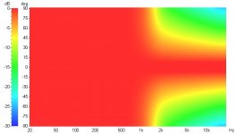
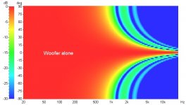
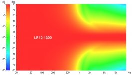
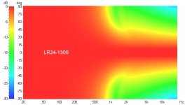
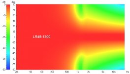
I had some time and curiosity got the best of me so I did some polar maps with crossovers (acoustic slope) from 6dB/oct to 96dB/oct. They're using a 15" woofer and the QSC 90x60 horn. I stuck with 1300Hz for all of them because there's a directivity mismatch there. Crossing lower would give smoother patterns but going too much lower would strain the tweeter on that horn. These are normalized to the on-axis response so they aren't showing the actual on-axis response of the drivers.


Attachments

- Home
- Loudspeakers
- Multi-Way
- Geddes on Waveguides